There are well-known Bluetooth transmitters on the market like the HC-05 or the HC-06. Then appeared the JDY-30 and JDY-31. What can we say about them?
There is very little information available on these modules, and they are contradictory.
The name: JDY-30 vs JDY-31
The sellers seem to use the 2 names interchangeably. In fact there are two different types of module, on the left the JDY-30 and on the right the JDY-31:
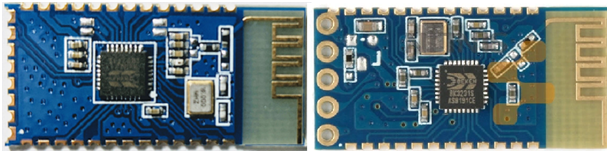
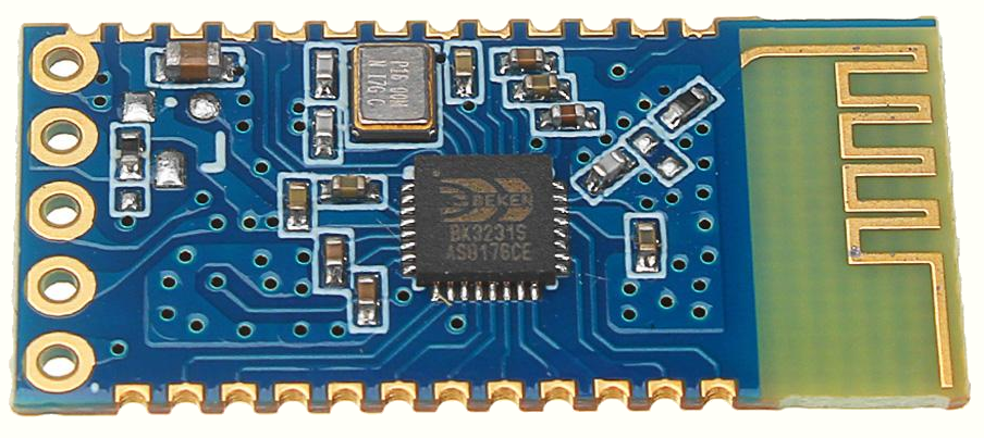
The JDY-30 seems to be the first to appear, and uses the BK3231 chip. It is recognizable because it does not have the holes to solder a header. This circuit seems obsolete and sellers replace it with a JDY-31.
The JDY-31 appears to be newer and uses the BK3231S chip. It is also more convenient with the possibility of directly soldering a header.
Documentation
I couldn’t find an official doc, and all of them have roughly the same information, regarding V1.2 or V1.3 software. Some documents mix the information on the two types of modules.
One thing is certain: the module is configurable with AT commands. But what set of commands is available?
These are slave modules (like the HC-06).
JDY-31_manuel_2.pdf: Unknown source, seems to document the JDY-31.
jdy-30-bluetooth-module.pdf: Source KO4BB. It is not clear if this document apply to JDY-30 or JDY-31.
Tests
The information available on the net did not allow me to get started easily. But on reflection things have become clearer.
The test set-up
It is a priori easier to experiment by connecting the module to a serial/USB converter then to a PC, than directly to a microcontroller.
I am using a serial/USB converter which has a jumper to connect its VCC pin to the 5V from USB or to the 3.3V of the FTDI232. It is convenient !
The JDY-31 module is to be supplied with 3.3V, which is handy to connect it to a Cortex-M type microcontroller such as an STM32.
The connections to be made:
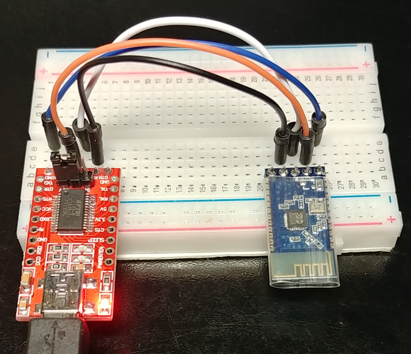
There are no LEDs on the JDY-31 module. It’s confusing at first.
Bluetooth pairing
As soon as the module is powered on, it appears in the list of Bluetooth connections on the smart phone, and it can be paired.
The BlueTerm Bluetooth terminal can connect to the module.
On the PC I run Putty in 9600 baud and bingo! A character typed in Putty appears on the phone, and a character typed on the phone appears in Putty.
What have we learned?
- The connection in data mode is automatic, and by default.
- Characters are transmitted as soon as they are supplied, in both directions.
- CR, LF or CRLF are transmitted like the other characters.
This contradicts some websites which say that the module transmits only after receiving a CRLF, which would imply that it cannot transmit arbitrary binary data since it buffers the data and CR and LF have special meaning.
Additional tests were carried out with a Bluetooth terminal allowing the transmission and reception of hexadecimal characters (Bluetooth Terminal – Qwerty):
Arbitrary hexadecimal characters are transmitted as soon as they are supplied, without requiring a CRLF.
In conclusion of the data transmission tests, the Bluetooth connection is easy, and the module seems able to transmit any type of data
CAVEAT: In data mode (or connected state) one AT command is accepted! If you send AT+DISC you get an answer: +DISC:SUCCESS, then you can no longer send data. But the link is not completely broken, the remote master remains connected and you can continue to receive the data it transmits.
It sounds completely silly. Once connected, no AT command should be possible, and if we wanted to be able to force a disconnection from the slave side, we would have to use an I/O pin. And in this case the disconnection should be complete: the master should notice it and the module should refuse to receive.
This aberrant behavior could cause many people not to use this module.
AT commands
The module can only be configured if it is not in data mode, and therefore not connected.
In the test configuration with a serial/USB converter:
- Using Putty: No response from the module to AT commands!
- Even using a Putty modified to allow CRLF to be sent by the Enter key. This is checked with the oscilloscope.
- A test at 38400 baud as indicated by some sources: nothing.
- Same tests with Tera Term: still no response from the module.
Thinking about the experiences of others, I tell myself that everyone who was successful in using the module was using an Arduino terminal. What is the difference with Putty and Tera Term?
This is because the Arduino terminal only transmits characters after pressing the Enter key and not character by character as you type!
How to do this with Putty or Tera Term which does not allow this mode (I have never installed Arduino …).
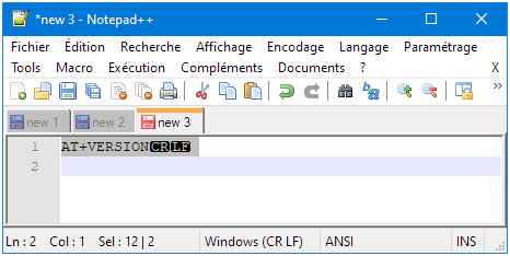
I type the command in Notepad ++, select it including CRLF, and copy it to the clipboard:
In Tera Term right click and OK:
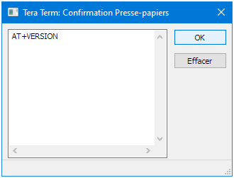
and … Tadaaa
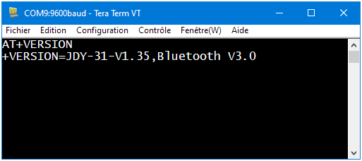
What have we learned?
- The AT commands must be issued with joining characters (no delay between characters) followed by CRLF.
- The module version is V1.35.
The first point explains why only those using an Arduino terminal managed to use this module.
And this led them to believe that the module buffers the data until CRLF is sent. But this is a feature of the Arduino terminal, not of the JDY-31 module.
Note: Putty does not allow pasting the clipboard => not usable to configure this module.
EDIT: Later I found a small terminal emulator suitable for this use: Termite from CompuPhase.
Some tests on the other commands tell us that:
- The AT command does not respond.
- The AT+BAUD command allows you to change the baud rate. But the module must be powered up again for this to be taken into account.
- The maximum accepted baud rate is 9 (128000 bauds). Far from what I expected (one of the documents allows up to C or 1382400 baud).
- There should be no space between the command and the argument. For example, to configure a baud rate of 19200: “AT+BAUD5”
Conclusion
The JDY-31 module allows easy Bluetooth connection, and the module seems able to transmit any type of data with the exception of the word “AT+DISC\ r\ n”.
The transmission speed is not as fast as expected.
The configuration using AT commands has one constraint: the characters must be transmitted joined, and followed by CRLF (As for HC-05).
The results of this test may only be valid for version 1.35. There are several versions in circulation, probably with different characteristics. This is the downside of ridiculously cheap, and therefore poorly documented modules, and buying them is like playing the lottery…
The HC-05 appears to have a better design and to be more mature.
The board that was sold to me as JDY-31 has a BK3432 instead of a BK3231S. Many of the passives are in the same spot as on your JDY-31, but there are differences because of the different pinout of the chip. The AT+VERSION command says “+VERSION=JDY-31A-V2.241,Bluetooth V3.0+BLE”. A photo can be found on AliExpress in the description of item 33064163778. Only the photos without the baseboard show the BK3432 variant.
Actually I was hoping for a BK3231S when buying the module since there people have already found an SDK and documented how to replace the firmware. But I guess Jindouyun had to switch chips because the BK3231S is no longer listed on the Beken website.