How to design a generic startup file and a configurable linker script
A startup file is a piece of code written in assembly or C language that executes on reset before the main() function of our embedded application.
It performs some hardware settings of the microcontroller and initializes the RAMs content (some from the FLASH) so that the user application can run.
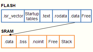
The content of these memories is divided into regions which must be judiciously placed. This organization is specified to the linker by a script file.
The startup code must therefore understand what is generated by the linker in order to copy the portions of FLASH to the right places in the RAM.
MCUs are becoming more and more complex: Several domains of SRAM, code execution in RAM, backup RAM… It is therefore more and more difficult to manage startup file and linker script for several MCUs or architectures.
There are multiple ways to design a startup file and the corresponding linker script. The objective of this blog is not to cover all the possibilities of the linker script but to limit itself to explaining the following points:
- Design a generic startup file that does not need to be modified when the script file evolves, or when it is used on another MCU family. The Cortex-M architecture makes it easy to write it in C.
- The linker script must provide for standard cases (data, BSS), but also more specific cases: code in RAM, data in backup RAM, etc.
- How to handle the special cases introduced by C ++.
The example is based on GNU tools (GCC and linker) and applies to the STM32F429 MCU. It is easily portable to other Cortex-M MCU like the STM32 families.
Design of a generic startup file
The startup file contains a single start_() function, which provides:
- The necessary hardware initialization. This initialization must be reduced to a minimum: in general initialization of the clocks of the used SRAM domains, possible inhibition of the watchdog, etc. This initialization is very dependent on the MCU and the application, so it is performed by a function outside the startup file (The function is part of the BSP).
- The copy of the initialized regions of the SRAM from the FLASH. There may be several data regions initialized in SRAM, CCR RAM or backup RAM for example. There can also be multiple code regions in SRAM, since some MCUs have multiple SRAM domains.
- Initializing to 0 the data regions to be initialized to 0 (generally called .bss). As for the initialized data there can be several regions in different SRAM, or CCR or backup RAM.
- Call the entry point of the application.
The startup function is called directly by the reset handler. Thus, the _start () function does not rely on the code of the reset handler, which also becomes generic.
// The reset handler is in the vector.c file

extern void __attribute__((noreturn)) start_ (void);

void __attribute__ ((section(".isr_handlers"), noreturn, naked)) Reset_Handler (void)
{
	start_ () ;
}
The principle used to get a generic start_() function consists in having the linker build two tables which describe the different regions of RAM, and which will be used by the startup function. Since the specific information comes exclusively from the linker script, the startup function can be completely generic.
The specific information relates only to the addresses of the tables. The startup code does not use the classic variables such as _sdata or __data_start__, which are not standardized, and become too numerous when multiple regions are used. This is one of the great advantages of this method.
Processing of initialized regions
The first table describes the initialized regions (code and data). These regions must be copied from FLASH to SRAM. An element of this table contains three words:
- The FLASH address of the source of the copy
- The RAM address of the copy destination
- The RAM address following the end of the region (the address following the last copied element).
The linker builds the table, and provides the start and end addresses of this table. The code to copy these regions is:
extern uint32_t	__data_regions_array_start ;
extern uint32_t	__data_regions_array_end ;

// Copy multiple DATA or CODE sections from FLASH to SRAM.
// Iterate and copy word by word.
// It is assumed that the pointers are word aligned.
for (p = & __data_regions_array_start ; p < & __data_regions_array_end ; )
{
	uint32_t * from 	= (uint32_t *) (* p++) ;
	uint32_t * region_begin	= (uint32_t *) (* p++) ;
	uint32_t * region_end 	= (uint32_t *) (* p++) ;

	while (region_begin < region_end)
	{
		* region_begin++ = * from++ ;
	}
}
Processing of regions initialized to 0
The second table describes the regions to be initialized to 0. An element of this table contains two words:
- The FLASH address of the start of the region
- The RAM address following the end of the region.
The linker builds the table, and provides the start and end addresses of the table. The code to initialize these regions is:
extern uint32_t	__bss_regions_array_start ;
extern uint32_t	__bss_regions_array_end ;

// Zero fill multiple BSS sections
// Iterate and copy word by word.
// It is assumed that the pointers are word aligned.
for (p = & __bss_regions_array_start ; p < & __bss_regions_array_end ; )
{
	uint32_t * region_begin	= (uint32_t *) (* p++) ;
	uint32_t * region_end	= (uint32_t *) (* p++) ;

	while (region_begin < region_end)
	{
		* region_begin++ = 0u ;
	}
}
In a full startup function, when the application ends and the main() function returns, it would run all the cleanup routines (mainly C ++ static destructors). But as here the main() function never returns the cleanup routines are ignored.
Once written, this startup function will no longer have to be changed when changing MCUs or adding sections.
Since it is agreed to set the pins to 0 or 1 independently of each other using the BSRR and BRR registers, there is no longer any constraint on the arrangement of the data bits on the GPIOs.
The complete code for the startup function
// These symbols are provided by the linker.

extern uint32_t	__data_regions_array_start ;
extern uint32_t	__data_regions_array_end ;
extern uint32_t	__bss_regions_array_start ;
extern uint32_t	__bss_regions_array_end ;

// ------------------------------------------------------------------------
// Forward declarations

void	start_		(void);	// Entry point at startup

void	bspMain_		(void) ;	// Entry function in BSP
void	bspSystemInit_	(void) ;	// Very early minimum hardware init

// ------------------------------------------------------------------------
// This is the place where the Cortex-M reset handler goes
//
// After Reset the Cortex-M processor is in Thread mode,
// priority is Privileged, and the Stack is set to Main.

void __attribute__ ((section(".startup"),noreturn))	start_ (void)
{
	uint32_t 	* p ;

	// Very early minimum hardware initialization
	// If you use ITCM, DTCM, you must enable clocks of theses devices
	// It also may be the place to stop watch dog
	// Or enable external RAM
	bspSystemInit_ () ;

	// Copy multiple DATA or CODE sections from FLASH to SRAM.
	// Iterate and copy word by word.
	// It is assumed that the pointers are word aligned.
	for (p = & __data_regions_array_start ; p < & __data_regions_array_end ; )
	{
		uint32_t * from 	= (uint32_t *) (* p++) ;
		uint32_t * region_begin	= (uint32_t *) (* p++) ;
		uint32_t * region_end 	= (uint32_t *) (* p++) ;

		while (region_begin < region_end)
		{
			* region_begin++ = * from++ ;
		}
	}

	// Zero fill multiple BSS sections
	// Iterate and copy word by word.
	// It is assumed that the pointers are word aligned.
	for (p = & __bss_regions_array_start ; p < & __bss_regions_array_end ; )
	{
		uint32_t * region_begin	= (uint32_t *) (* p++) ;
		uint32_t * region_end	= (uint32_t *) (* p++) ;

		while (region_begin < region_end)
		{
			* region_begin++ = 0u ;
		}
	}

	// Call the BSP entry point
	bspMain_ () ;	// Will never return

	// Should never reach this
	while (1)
	{
	}
}
The bspMain() function have to continue the MCU initialization : enable caches and prefetch, set the system clock, enable fault exceptions, etc.
The configurable linker script file
The linker script can be separated into two parts:
- The definition of the memory spaces
- The organization of the content of the memory spaces.
For an STM32F429, the definition of memory spaces can be:
/*
 * Memory Spaces Definitions.
 *
 * Update for a specific board.
 *   FLASH.ORIGIN : starting address of flash
 *   FLASH.LENGTH : length of flash
 *   RAM.ORIGIN   : starting address of main RAM
 *   RAM.LENGTH   : length of main RAM
 *
 * The values below can be addressed in linker scripts
 * using functions like 'ORIGIN(RAM)' or 'LENGTH(RAM)'.
 */

/* Memory definitions for  STM32F427/37xx ,STM32F429/39xx
 * Adjust your amount of FLASH
 *
 * Can't execute code from CCMRAM
 * Can execute code from SRAM1 (112 KB) : 0x2000 0000 - 0x2001 BFFF
 * Can execute code from external memory (FSMC/FMC)
 */

MEMORY
{
	FLASH         (rx) : ORIGIN = 0x08000000, LENGTH = 1024K
	FLASHB2       (rx) : ORIGIN = 0x00000000, LENGTH = 0
	RAM          (xrw) : ORIGIN = 0x20000000, LENGTH = 192K
	CCMRAM        (rw) : ORIGIN = 0x10000000, LENGTH = 64K
	BKPRAM        (rw) : ORIGIN = 0x40024000, LENGTH = 4K

	EXTMEMB0     (xrw) : ORIGIN = 0x00000000, LENGTH = 0
	EXTMEMB1     (xrx) : ORIGIN = 0x00000000, LENGTH = 0
	EXTMEMB2     (xrw) : ORIGIN = 0x00000000, LENGTH = 0
	EXTMEMB3     (xrw) : ORIGIN = 0x00000000, LENGTH = 0
}
For the organization of the sections in the different regions of RAM, these sections must be named. Here we will use the following section names:
.text_RAM
.data_CCMRAM
.bss_CCMRAM
.noinit_CCMRAM
.data_BKPRAM
.bss_BKPRAM
.noinit_BKPRAM
The section of the code in SRAM, must be placed at the start of SRAM.
The section of initialized data in CCM RAM
The section of 0 initialized data in CCM RAM
The section of uninitialized data in CCM RAM
The section of initialized data in backup RAM
The section of 0 initialized data in backup RAM
The section of uninitialized data in backup RAM
These section names must be used in the declaration of functions, or data, for example:
// To set a function in RAM section:
__attribute__ ((section(".text_RAM")))      void ramFunction (void)

// To set an initialized data in a CCMRAM or BKPRAM:
__attribute__ ((section(".data_CCMRAM")))	int32_t	nbData = 3 ;
__attribute__ ((section(".data_BKPRAM")))	int32_t	nbData = 3 ;

// To set a zeroized data in CCMRAM or BKPRAM:
__attribute__ ((section(".bss_CCMRAM")))	int32_t	nbData ;
__attribute__ ((section(".bss_BKPRAM")))	int32_t	nbData ;

// To set an uninitialized data in RAM, CCMRAM or BKPRAM:
__attribute__ ((section(".noinit")))		int32_t	nbData ;
__attribute__ ((section(".noinit_CCMRAM")))	int32_t	nbData ;
__attribute__ ((section(".noinit_BKPRAM")))	int32_t	nbData ;
The construction of tables intended for the startup function
To build the tables intended for the startup function, we define a section called .inits in the SECTIONS command. Two tables will be built, one for the initialized regions and one for the zeroized regions.
For the table of initialized regions there is a table element for each section of code in RAM and one element for each section of initialized data in RAM.
A table element contains three pieces of information:
from (LOADADDR (section)) // in FLASH
region_begin (ADDR (section)) // in RAM
region_end (ADDR (section) + SIZEOF (section)) // in RAM
In our case this gives:
/* Memory regions initialization tables. */

__data_regions_array_start = . ;

/* Code in RAM */
LONG(LOADADDR(.text_RAM)) ;
LONG(ADDR(.text_RAM)) ;
LONG(ADDR(.text_RAM)+SIZEOF(.text_RAM)) ;

/* Initialized data in RAM */
LONG(LOADADDR(.data)) ;
LONG(ADDR(.data)) ;
LONG(ADDR(.data)+SIZEOF(.data)) ;

/* Initialized data in CCM RAM */
LONG(LOADADDR(.data_CCMRAM)) ;
LONG(ADDR(.data_CCMRAM)) ;
LONG(ADDR(.data_CCMRAM)+SIZEOF(.data_CCMRAM)) ;

/* Initialized data in backup RAM */
LONG(LOADADDR(.data_BKPRAM)) ;
LONG(ADDR(.data_BKPRAM)) ;
LONG(ADDR(.data_BKPRAM)+SIZEOF(.data_BKPRAM)) ;

 __data_regions_array_end = . ;
For the table of regions initialized to 0 there is a table element for each data section initialized to 0 in RAM. A table element contains two pieces of information:
region_begin (ADDR (section)) // in RAM
region_end (ADDR (section) + SIZEOF (section)) // in RAM
In our case this gives:
__bss_regions_array_start = . ;

LONG(ADDR(.bss)) ;
LONG(ADDR(.bss)+SIZEOF(.bss)) ;

LONG(ADDR(.bss_CCMRAM)) ;
LONG(ADDR(.bss_CCMRAM)+SIZEOF(.bss_CCMRAM)) ;

LONG(ADDR(.bss_BKPRAM)) ;
LONG(ADDR(.bss_BKPRAM)+SIZEOF(.bss_BKPRAM)) ;

__bss_regions_array_end = . ;
Then, as usual, each section must be declared. Example:
/* The code section in RAM */
.text_RAM : ALIGN(4)
{
	*(.text_RAM .text_RAM.*)
	. = ALIGN(4) ;
} > RAM AT>FLASH


/* Initialized data in CCMRAM */
.data_CCMRAM : ALIGN(4)
{
	*(.data_CCMRAM .data_CCMRAM.*)
	. = ALIGN(4) ;
} > CCMRAM AT>FLASH

/* Zeroized data in CCMRAM*/
.bss_CCMRAM (NOLOAD) : ALIGN(4)
{
	*(.bss_CCMRAM .bss_CCMRAM.*)
	. = ALIGN(4) ;
} > CCMRAM

/* Non initialized data in CCMRAM */
.noinit_CCMRAM (NOLOAD) : ALIGN(4)
{
	*(.noinit_CCMRAM .noinit_CCMRAM.*)
	. = ALIGN(4) ;
} > CCMRAM
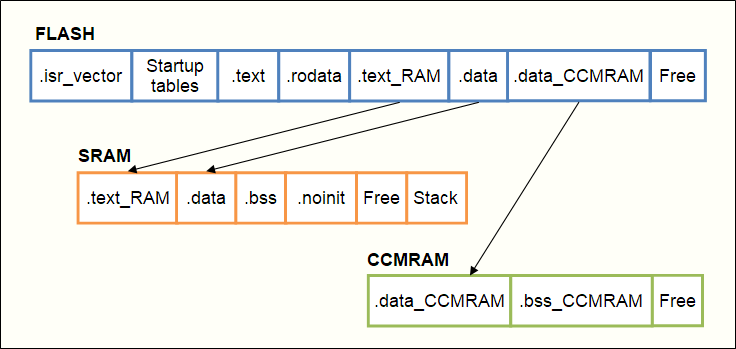
An example of the input section layout in FLASH, and the output sections layout in the different RAM regions once copied:
Special cases introduced by C++
C++ generates particular sections:
- A “preinit” table of initialization functions to call before executing constructors
- An “init” table of functions for constructors of static objects.
- A “fini” function table for static object destructors. This array is ignored here since the application never ends.
To declare these tables in the linker’s script file, add the following lines to the .inits section:
/*--------------------------------------------------------------------------
 * The preinit code, i.e. an array of pointers to initialization
 * functions to be performed before constructors.
 */
. = ALIGN (4) ;
PROVIDE_HIDDEN (__preinit_array_start = .) ;

/* The application inits. If you need to enforce some order in
 * execution, create new sections before this.
 */
KEEP (*(.preinit_array .preinit_array.*))

PROVIDE_HIDDEN (__preinit_array_end = .) ;

/*--------------------------------------------------------------------------
 * The init code, i.e. an array of pointers to static constructors.
 */
. = ALIGN (4) ;
PROVIDE_HIDDEN (__init_array_start = .) ;
KEEP (*(SORT_BY_INIT_PRIORITY (.init_array.*)))
KEEP (*(.init_array*))
PROVIDE_HIDDEN (__init_array_end = .) ;

/*--------------------------------------------------------------------------
 * The fini code, i.e. an array of pointers to static destructors.
 */
. = ALIGN (4) ;
PROVIDE_HIDDEN (__fini_array_start = .) ;
KEEP (*(SORT_BY_INIT_PRIORITY (.fini_array.*)))
KEEP (*(.fini_array*))
PROVIDE_HIDDEN (__fini_array_end = .) ;
Constructors can use high level resources: mutex, malloc, etc.
We must therefore call the static constructors once all the necessary resources are initialized, probably in the main() function. This explains why it cannot be done in the startup function.
In the AdAstra RTOS this is done by the aaMain() function, after the kernel initialization and before the first application task is created. The code to run to use the tables generated by C ++ is:
The code to run to use the tables generated by C ++ is:
// These symbols are provided by the linker.
// C++ initializations.

extern void	(* __preinit_array_start [])	(void) ;
extern void	(* __preinit_array_end   [])	(void) ;
extern void	(* __init_array_start    [])	(void) ;
extern void	(* __init_array_end      [])	(void) ;

// Iterate over all the preinit/init routines:
// Call the standard library initialization (mandatory for C++ to
// execute the constructors for the static objects).
// Can't be called sooner: use malloc()
{
	int count ;
	int ii ;

	count = __preinit_array_end - __preinit_array_start ;
	for (ii = 0 ; ii < count ; ii++)
	{
		__preinit_array_start [ii] () ;
	}

	count = __init_array_end - __init_array_start;
	for (ii = 0 ; ii < count ; ii++)
	{
		__init_array_start [ii] () ;
	}
}
Conclusion
You know how to design a generic startup file and a configurable linker script. It is easy to define an additional region and have it taken into account by the startup function:
- Choose a section name.
- Add an element in one of the region description tables.
- Declare the section.
- Use the section name to declare function or data in the code.
This method is successfully used by AdAstra-Soft for the AdAstra RTOS distributions. It greatly facilitated porting to a new MCU.
Some links
Download the startup and script files: startup_and_ld.zip
The GNU linker manual:
https://sourceware.org/binutils/docs/ld/
Interesting LD script features :
https://tty.uchuujin.de/2016/03/stm32-from-scratch-enableing-c-c++-features/
https://embedds.com/programming-stm32-discovery-using-gnu-tools-startup-code/
https://embedds.com/programming-stm32-discovery-using-gnu-tools-linker-script/
according to the stm32l4 and g4 family reference manuals,you should map ram with code to 0x00000000 so thce cpu can access it over its i and d bus.
when i do that i have to copy the code from flash to the 0x200000;range before changing the mapping. however no matter what variation I try the cpu locks up
do you have a working example of running code from the rrmapped ram region at 0x00000000?
theoretically it should also work to run code from segments declared >REMAPPED AT >FLASH
with origin(remapped)= 0x0 but i can’t get that to work either
I didn’t try to execute from remapped RAM.
Here is what I would do:
– Define a memory named RAM0 with the address 0
– Set the code in a section named text_RAM0
– Add a table entry to copy code of the section test_RAM0 from flash to RAM0
In the startup file remap the RAM to 0 at the very beginning of the _start() function.
You can have a look to this how to: https://community.st.com/t5/stm32-mcus/how-to-place-and-execute-stm32-code-in-sram-memory-with/ta-p/49528
You can also ask the question in the STM32 community forum: https://community.st.com/t5/stm32-mcus-products/bd-p/stm32-mcu-products-forum