How to effectively use a HD44780 based display with an STM32 MCU?
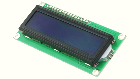
The 1602 LCD displays are very common and inexpensive. They are based on a controller compatible with the venerable HD44780, which is very simple to use.
How to effectively use a HD44780 based display with an STM32 MCU, like the Blue Pill or the Black Pill?
A display based on an HD44780 has some advantages:
- Very cheap
- Very easy to use
It also has some disadvantages:
- Uses many pins: 7 to 11
- It is slow
How to minimize these disadvantages using the special features of STM32 MCUs?
Slowness
The instructions executed by the controller have a variable duration, and during this time the controller should not be addressed. In many implementations a fixed delay is added after each command to take this into account.
However, the controller has a BUSY flag on pin D7 which can be read to limit the waiting time to a minimum. On the other hand, the STM32 makes it easy to switch the input / output mode of a pin. We will therefore use this functionality to read the BUSY flag of the controller after each command to minimize the time between two commands.
Direct access to the GPIO registers is simple on the STM32s, therefore direct access to the MCU registers is used. This avoids having to use heavy and slow libraries like the HAL.
The pins used by the display
First the number of pins
The controller allows the use of 6, 7 or 11 pins. Using 11 pins (with 8-bit data bus) is more efficient than using a 4-bit data bus. However, the gain is minimal compared to the processing time of each command by the controller: approximately 37 µs. In addition the number of pins available on the MCU is limited. So we will use 7 pins:
- RS : Data / Command
- WR : To read the BUSY flag
- E : Strobe
- D4-D7 : The data bus
Which pins of the STM32 to use?
For commands (RS, WR, E) no problem: they are used independently and can therefore be assigned to any GPIO of the MCU.
For the data bus, it can be tempting to use 4 contiguous pins on the same GPIO port. But this is very restrictive:
1) all the pins of the MCUs have several functions and it is rare to be able to have 4 contiguous free pins.
2) You must be able to position the data on these pins atomically.
This last point concerns multi-tasking applications, or interruptions routines. You cannot read / modify / write on the GPIO ports. This is why the GPIO ports have registers BSRR and BRR which allow to put at 1 or at 0 a pin in an atomic way.
Since it is agreed to set the pins to 0 or 1 independently of each other using the BSRR and BRR registers, there is no longer any constraint on the arrangement of the data bits on the GPIOs.
All pins on the display can therefore be connected to any unused pins on the MCU.

How to do this?
You must declare the pins used, for example:
// Define pins, modify these definitions according to your wiring

#define	RS_PORT		GPIOA
#define	RS_PIN		10

#define	RW_PORT		GPIOC
#define	RW_PIN		4

#define	E_PORT		GPIOB
#define	E_PIN		5

#define	D4_PORT		GPIOB
#define	D4_PIN		13

#define	D5_PORT		GPIOB
#define	D5_PIN		15

#define	D6_PORT		GPIOB
#define	D6_PIN		14

#define	D7_PORT		GPIOB
#define	D7_PIN		10
You must then declare the macros that will position the pins at 0 or 1.
Macros are used to generate inline code, and they are too simple to justify inline functions. These declarations are independent of the STM32 model used.
In fact these declarations are a little more complex for STM32F4. In this family there is no BRR register. The real story: BRR and BSRR are 16-bit registers, but stm32f4xx.h defines them as a single 32-bit register. Sigh…
#define	rsSet()		RS_PORT->BSRR = (1u << RS_PIN)
#define	rsClear()	RS_PORT->BRR  = (1u << RS_PIN)

#define	rwSet()		RW_PORT->BSRR = (1u << RW_PIN)
#define	rwClear()	RW_PORT->BRR  = (1u << RW_PIN)

#define	eSet()		E_PORT->BSRR  = (1u << E_PIN)
#define	eClear()	E_PORT->BRR   = (1u << E_PIN)

#define	d4Set()		D4_PORT->BSRR = (1u << D4_PIN)
#define	d4Clear()	D4_PORT->BRR  = (1u << D4_PIN)

#define	d5Set()		D5_PORT->BSRR = (1u << D5_PIN)
#define	d5Clear()	D5_PORT->BRR  = (1u << D5_PIN)

#define	d6Set()		D6_PORT->BSRR = (1u << D6_PIN)
#define	d6Clear()	D6_PORT->BRR  = (1u << D6_PIN)

#define	d7Set()		D7_PORT->BSRR = (1u << D7_PIN)
#define	d7Clear()	D7_PORT->BRR  = (1u << D7_PIN)
With these definitions it is easy to manage the pin’s states. For example to send a command to the controller, which requires generating a pulse on pin E:
//------------------------------------------------------------
// Generate E pulse

static void ePulse (void)
{
	bspDelayUs (1) ;		// For data setup
	eSet () ;
	bspDelayUs (1) ;
	eClear () ;
}
//------------------------------------------------------------
// Send command to LCD

static	void hdCmd (uint8_t cc)
{
	setDataPort (cc >> 4) ;		// Get upper nibble
	rsClear () ;				// Set LCD to instruction mode
	ePulse () ;					// E strobe

	setDataPort (cc) ;			// Get lower nibble
	ePulse () ;					// E strobe

	hdWaitForBusy () ;
}
The setDataPort () function which allows writing a nibble to the data port D7-D4 is hardly more complicated. The function is not that slow: around 1 µs on an STM32F103 at 72 MH.
// Set the low nibble of the data to the data output port

static void setDataPort (uint32_t data)
{
	if ((data & 0x08u) == 0u)
			d7Clear ()
	else	d7Set ()

	if ((data & 0x04u) == 0u)
			d6Clear ()
	else	d6Set ()

	if ((data & 0x02u) == 0u)
			d5Clear ()
	else	d5Set ()

	if ((data & 0x01u) == 0u)
			d4Clear ()
	else	d4Set ()
}
The last complex function is the initialization of the GPIO pins and of the LCD:
// Initialize the LCD device

void hdInit (void)
{
	// Initialize GPIO ports
	hdGpioInit (RS_PORT, RS_PIN) ;
	hdGpioInit (RW_PORT, RW_PIN) ;
	hdGpioInit (E_PORT,  E_PIN) ;
	hdGpioInit (D4_PORT, D4_PIN) ;
	hdGpioInit (D5_PORT, D5_PIN) ;
	hdGpioInit (D6_PORT, D6_PIN) ;
	hdGpioInit (D7_PORT, D7_PIN) ;

	// Reset HD44780
	rsClear () ;
	rwClear () ;
	bspDelayUs (40000) ;	// Min 40ms

	setDataPort (0x03u) ;
	ePulse () ;
	bspDelayUs (6000) ;		// Min 5ms

	setDataPort (0x03u) ;
	ePulse () ;
	bspDelayUs (200) ;		// Min 100 us

	setDataPort (0x03u) ;
	ePulse () ;
	bspDelayUs (200) ;

	setDataPort (0x02u) ;	// Enable 4-Bit Mode
	ePulse () ;
	hdWaitForBusy () ;

	hdCmd (0x28) ;		// Set Interface Length: 4 bits, 2 lines, 5x7 font
	hdCmd (0x08) ;		// Display off
	hdCmd (0x01) ;		// Clear display
	hdCtrl = 0x0Cu ;	// Display on, cursor off, no blink
	hdCmd (hdCtrl) ;
	hdCmd (0x06) ;		// Entry mode: Move cursor after each data
}
The functions already seen use functions specific to the STM32 model used. In particular, you must be able to configure D7 as output and also as input to be able to read the BUSY flag of the HD44780. For an STM32F103 this gives:
//------------------------------------------------------------
// Must be adapted to your MCU

// For STM32F1xx MCU

#define		MODE_IN		0x04u
#define		MODE_OUT	0x02u
#define		MODE_MASK	0x0Fu

//------------------------------------------------------------
// Configure GPIO pins to output

static void hdGpioInit (GPIO_TypeDef * pGpio, uint32_t pin)
{
	// Enable port clock (without pointer arithmetic...)
	RCC->APB1ENR |= 1u << ((((uint32_t) pGpio - (uint32_t) GPIOA) / ((uint32_t) GPIOB - (uint32_t) GPIOA)) + RCC_APB2ENR_IOPAEN_Pos) ;

	// Initialize GPIO as output
	if (pin < 8)
	{
		pGpio->CRL = (pGpio->CRL & ~(MODE_MASK << (pin * 4))) | (MODE_OUT << (pin * 4)) ;
	}
	else
	{
		pGpio->CRH = (pGpio->CRH & ~(MODE_MASK << ((pin - 8) * 4))) | (MODE_OUT << ((pin - 8) * 4)) ;
	}
}

//------------------------------------------------------------
// To switch D7 to input, allows to check the HD44780 busy flag.

__ALWAYS_STATIC_INLINE	void	d7IsInput (void)
{
	#if (D7_PIN < 8)
	{
		D7_PORT->CRL = (D7_PORT->CRL & ~(MODE_MASK << (D7_PIN * 4))) | (MODE_IN << (D7_PIN * 4)) ;
	}
	#else
	{
		D7_PORT->CRH = (D7_PORT->CRH & ~(MODE_MASK << ((D7_PIN - 8) * 4))) | (MODE_IN << ((D7_PIN - 8) * 4)) ;
	}
	#endif
}

//------------------------------------------------------------
// To switch D7 to output

__ALWAYS_STATIC_INLINE	void	d7IsOutput (void)
{
	#if (D7_PIN < 8)
	{
		D7_PORT->CRL = (D7_PORT->CRL & ~(MODE_MASK << (D7_PIN * 4))) | (MODE_OUT << (D7_PIN * 4)) ;
	}
	#else
	{
		D7_PORT->CRH = (D7_PORT->CRH & ~(MODE_MASK << ((D7_PIN - 8) * 4))) | (MODE_OUT << ((D7_PIN - 8) * 4)) ;
	}
	#endif
}
The GPIO initialization is a bit more complicated on an F4, which uses 5 registers instead of 1.
Once all of this is defined it is very easy to implement the user API, for example:
// LCD clear

void    hdClear (void)
{
	hdCmd (1) ;
}
The delays
We can observe that some functions use delays of a few micro seconds. The function of the AdAstra-RTK BSP to generate such delays is:
//	Lets busy wait for delays of tens of microseconds
//	Force optimization level to be independent of the general setting
//	BEWARE: At low core frequency the 1us delay may be impossible

#if defined(__CC_ARM)
	#pragma push
	#pragma Otime
#else
	#pragma GCC push_options
	#pragma GCC optimize ("O3")
#endif

void bspDelayUs (uint32_t us)
{
	volatile uint32_t start = DWT->CYCCNT ;
	volatile uint32_t cycles = (bspTsMhzDiv * us) - 42u ;	// Remove some cycles for instructions

	while ((DWT->CYCCNT - start) < cycles) ;
}

#if defined(__CC_ARM)
	#pragma pop
#else
	#pragma GCC pop_options
#endif
Conclusion
Here is an efficient implementation of a 1602 library for stm32 or blue pill board. These LCD displays are based on an HD44780 controller which allows:
- Little constraint on pins to use MCU
- Timing optimized by direct access to the registers and the use of the BUSY flag of the controller.
- Easy portage between STM32 families.
On a STM32F103 at 72 MHz it was measured approximately 40 µs per character when displaying a chain.
The library hd44780 to use with AdAstra-RTK is available here. It supports F1xx/L1xx and other families (F4, F7, H7…)
The library is also available in the distribution packages of the “Download” page.
Some links
Beware: The displays are available in 3.3V and 5V.
With STM32 it is easier to use 3.3V displays: See here how to hack your 1602 display.
Strangely on my 1602 in 3.3V the J3 strap is open …