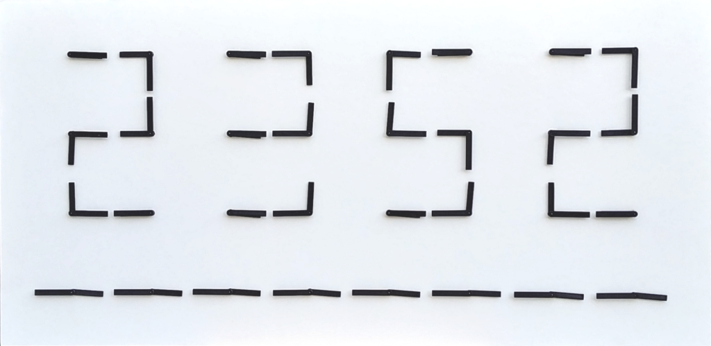
You have certainly seen these clock panels whose hands create moving and hypnotic shapes, for example: this
I wanted to make my own version of Clock Art, on a relatively small budget. This is the opportunity to carry out a project that involves several microcontrollers working together.
The design
It is necessary to define which motors to use to actuate the needles. A search on the internet quickly leads to VID-28 or X40 type engines. They are used in car dashboards and have two concentric axes. But there is a supplier on AliExpress who offers a modified motor (without stopper => 360°): BKA30D-R5. This is the motor I used.
It is necessary to be able to control these stepper type motors (1/12 ° per step). Rather than generating the complex signals from the MCU, I preferred to use a driver. The natural driver is the VID6606 which can drive 4 axes. I ordered 20, and unfortunately there were only 3 working.
I then ordered 20 compatible AX1201728SG drivers. They all worked!
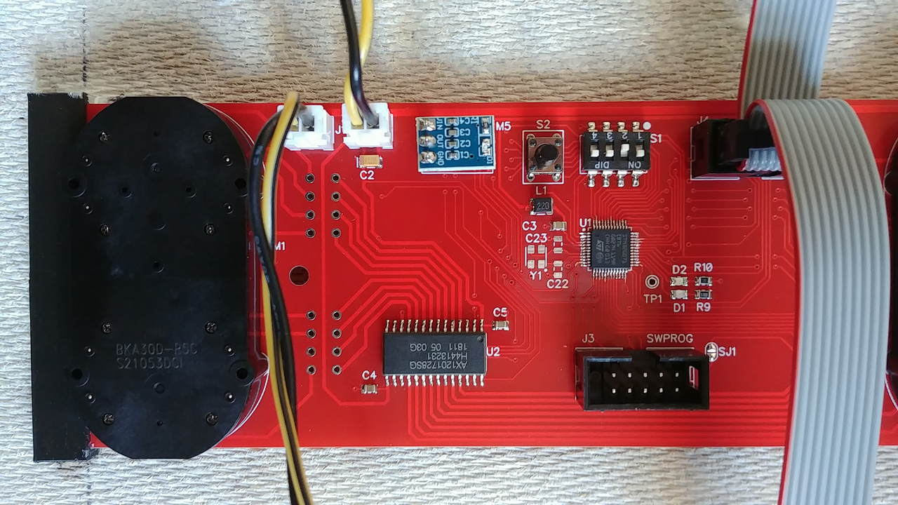
Using an MCU to drive each clock is oversized. It must be possible to manage 4 clocks, therefore 8 motors grouped together on a driver board with 1 single MCU. After compiling the constraints: 8 needles, analog inputs for Hall sensors, ease of soldering, price, and also availability at the end of 2020 which was starting to be problematic, the ideal candidate is the STM32G071CB (TQFP 48 pins).
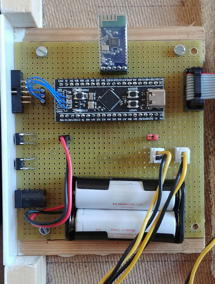
To synchronize the movements of all the driver boards, we need a master MCU. I am using an available “Black Pill” STM32F411 module. A Bluetooth module (JDY-31) is used to have a terminal type connection with a smart phone. This allows you to set the clock and trigger demonstrations without physical connection.
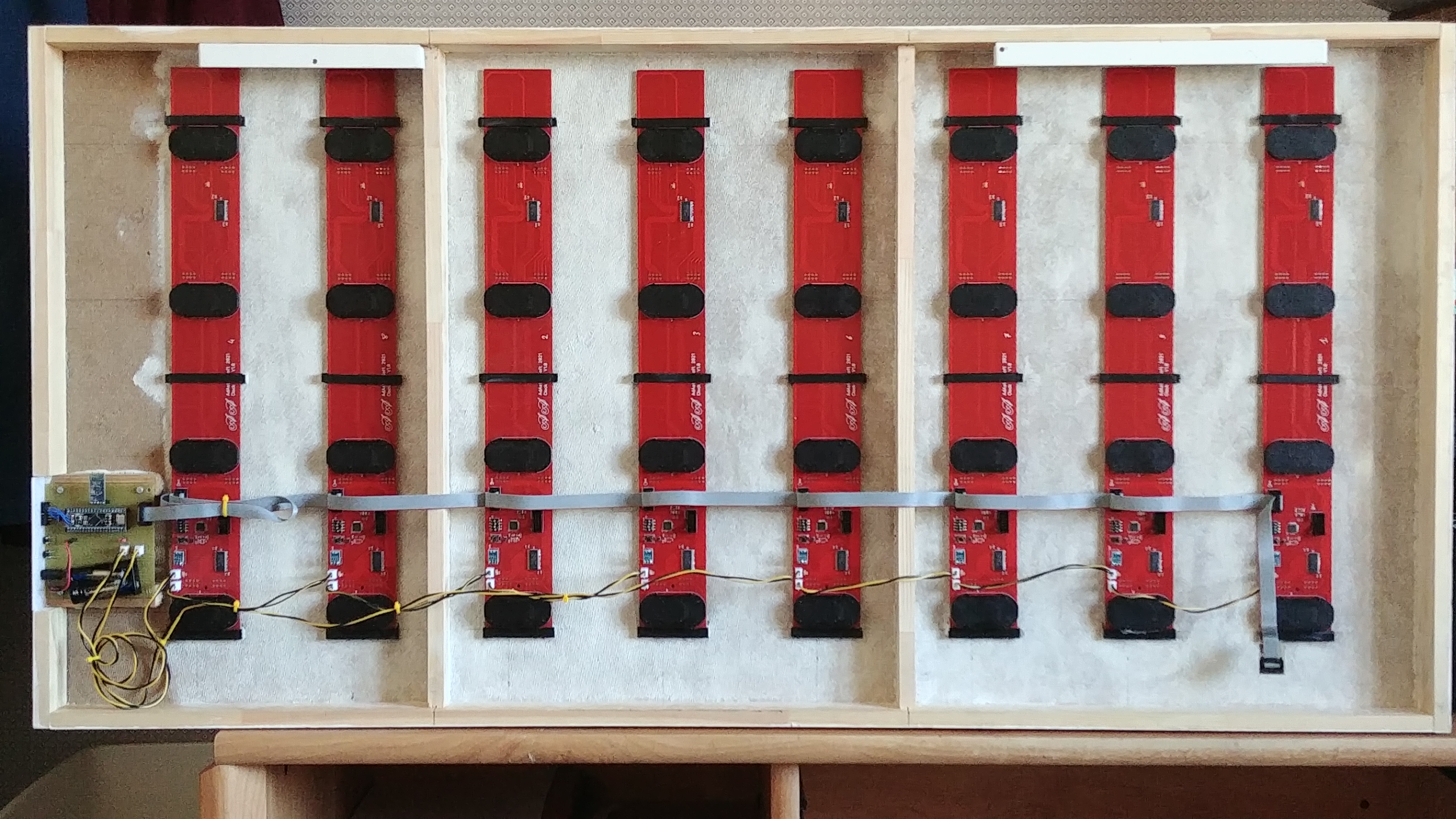
The architecture
The basic element is a driver board to manage the movements of 8 needles and equipped with an inexpensive MCU. Eight of these driver boards are arranged on a panel, to carry out the final assembly of 32 clocks.
The master’s commands are sent to the driver boards by SPI at 1 MHz. Only the MOSI line is used, in open drain with a pull up.
The master can ask the driver boards to position an output called ACK when all the needles have finished their operations. So the master can wait until the last driver board has finished its operations before sending the next orders. This output is configured as open drain (wired or) by the driver boards with an external pull up at the end of the line.
It is imperative that driver boards know where the needles are to properly respond to the master’s positioning commands. When powering up the hands are in a random position and driver boards should be able to determine their positions. I use Hall-effect sensors on the driver boards and magnets on the needles.
Which Hall-effect sensor to choose
Variants of Hall effect sensors
Unipolar digital Hall-effect sensor
A magnet presenting a south polarity (positive) magnetic field of sufficient strength will cause the sensor to switch to its on state. After it has been turned-on, the unipolar switch will remain turned-on until the magnetic field is removed and the sensor reverts to its off state.
Omnipolar digital Hall-effect sensor
Any polarity of a magnetic field of sufficient strength will cause the sensor to switch to its on state. After it has been turned-on, the omnipolar sensor will remain turned-on until the magnetic field is removed and the sensor reverts to its off state.
Bipolar digital Hall-effect sensor
A bipolar sensor requires a south polarity (positive) magnetic field of sufficient strength to switch to its on state, and a north polarity (negative) magnetic field of sufficient strength to switch to its off state.
Linear or analog Hall-effect sensor
This Hall-effect sensor analog output responds linearly to the applied magnetic flux density, and distinguishes the polarity of magnetic field direction. In the absence of magnetic flux the analog output is in the middle of the output range.
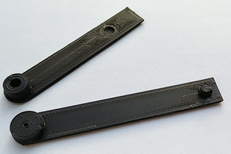
To use Hall-effect sensors, magnets must be placed under the clock hands. These magnets are small: a cylinder of 4mm diameter and 3mm height.
Having no idea of the strength of the magnetic flux of these magnets, it is risky to choose digital sensors. In addition, the STM32G071 has the analog inputs necessary to use analog sensors. So I use the linear Hall-effect sensors 49E in SOT23 package, operating at 5 V, and easily available.
The algorithm for calibrating the position of the hands is simple: make a complete turn with the hands, measuring the analog signal from the sensor on each step. For each hand the position where the signal is strongest is position 0 of this hand.
The power supply
Each motor rated current is 25mA. The rated current for 64 engines is therefore 1.6A. So a 5V 2.5A wall power supply is used.
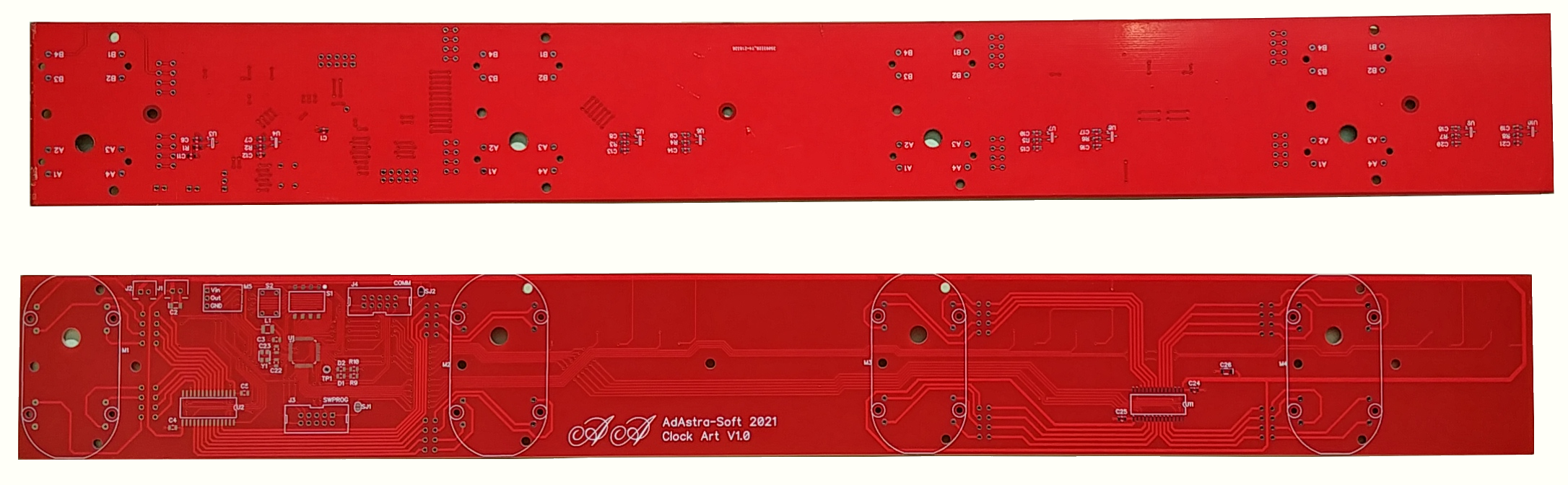
Making
The printed circuit of the driver boards is 50 cm long, the maximum allowed by the supplier. This involves the size of clocks and hands. It is designed to minimize wiring as much as possible, which is always a major source of breakdowns.
The needles are made by 3D printing.
The carpentry is delicate: the front plate must be thin (3 to 5 mm) because the axes of the motors are short.
Software
There are two softwares: one for the driver boards and one for the master board.
The software of the driver boards
The driver board software implements the needle movement commands, and some management commands for the driver board themselves:
- Look for the 0 of all hands
- Move the needle a number of steps, specifying direction and speed
- Wait a delay before executing the next command
- Move the needle a number of degrees from the current position, specifying direction and speed
- the needle to an absolute angle in degrees, specifying direction and speed
- Turn the LED on or off, very useful for early debugging
- Position the ACK output
- Reset of the ACK output
It may sound like a small set of commands, but by combining them the master can achieve a lot.
Download the driver board software project (TrueSTUDIO).
The software of the master board
The software on the master board is responsible for maintaining the time, which is a minimum for a clock! The RTC of the MCU (with a battery) is used to maintain the time when the panel is not powered.
The other task of the master board is to achieve the synchronized animation of the hands by sending command blocks to the driver boards:
– A data buffer is built with all the commands for all the driver boards. This data allows the driver boards to animate the hands for a few ms to a few seconds.
– The buffer is transmitted by SPI, and all the driver boards receive it at the same time.
– The driver boards search the received buffer for messages intended for the needles they manage, and place them in the specific queue for each needle.
– When its queue is not empty, each needle executes the commands it contains.
To run a particular show the master creates the correct data buffers and sends them to the driver boards at the correct rate. The driver boards have no idea what show is in progress: they only execute basic commands. Some shows have been implemented. But these are only examples: the only limit is the imagination (and the time to realize them …)
Download the master board software project (TrueSTUDIO).
Would you please post the link for the motors. I only find these motors with stoppers.
I bought these motors from AliExpress, but the link I used is dead.
Searching for “BKA30D-R5C 360” I found links like:
https://www.aliexpress.com/item/1005005491917600.html?spm=a2g0o.productlist.main.1.e9054731R9enWt&algo_pvid=79cdd525-f239-439c-990e-0a2d10547d89&algo_exp_id=79cdd525-f239-439c-990e-0a2d10547d89-0&pdp_ext_f=%7B%22order%22%3A%2229%22%2C%22eval%22%3A%221%22%7D&pdp_npi=4%40dis%21EUR%214.20%213.99%21%21%2131.00%2129.45%21%402103956a17374550089948579e6a54%2112000033293565024%21sea%21FR%211747637083%21X&curPageLogUid=ojokmGH8bSUb&utparam-url=scene%3Asearch%7Cquery_from%3A
https://www.aliexpress.com/item/1005008005295773.html?spm=a2g0o.productlist.main.3.e9054731R9enWt&algo_pvid=79cdd525-f239-439c-990e-0a2d10547d89&algo_exp_id=79cdd525-f239-439c-990e-0a2d10547d89-1&pdp_ext_f=%7B%22order%22%3A%221%22%2C%22eval%22%3A%221%22%7D&pdp_npi=4%40dis%21EUR%214.41%214.19%21%21%214.47%214.25%21%402103956a17374550089948579e6a54%2112000043232403269%21sea%21FR%211747637083%21X&curPageLogUid=OAWOB8bLGU8G&utparam-url=scene%3Asearch%7Cquery_from%3A
https://www.aliexpress.com/item/1005008233773931.html?spm=a2g0o.productlist.main.5.e9054731R9enWt&algo_pvid=79cdd525-f239-439c-990e-0a2d10547d89&algo_exp_id=79cdd525-f239-439c-990e-0a2d10547d89-2&pdp_ext_f=%7B%22order%22%3A%221%22%2C%22eval%22%3A%221%22%7D&pdp_npi=4%40dis%21EUR%212.50%213.49%21%21%2118.43%2125.80%21%402103956a17374550089948579e6a54%2112000044319447229%21sea%21FR%211747637083%21X&curPageLogUid=c1o9VANfmowa&utparam-url=scene%3Asearch%7Cquery_from%3A
These engines are advertised as “360°”
Good luck.
Thank you so much. I tried those advertised as 360 but the all have stops.
Would you still have the PCB files on hand?:)
Thank you!
You made a beautiful clock!
Hello,
Is it possible to publish the corresponding DipTrace schematic and PCB files with Gerber files for the ClockArt project here in addition to the software? Or is that ‘top secret’?
Best regards and many thanks.
Peter
I’ll send you the files.