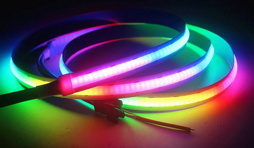
I made a wand with light animations using WS2812B and SPI with DMA.
The WS2812B are LEDs which actually contain 3 red, green and blue colored LEDs. We can configure the the light intensity of each of these LEDs independently, which theoretically allows an infinite number of colors (16 million).
You cans download the source code here
Electrical Specifications
Each color LED can consume up to 20mA. A WS2718B LED can therefore require up to 60mA. You must take this into account if you use a lot of LEDs: for example 60A for 1000 LEDs fully lit at the same time!
If a lot of LEDs are switched at the same time the current inrush can be important: a high value capacitor must be provided on the 5V supply.
The supply voltage is 5V. And the high level of the control signal must be greater than 0.7x5V = 3.5V. This is incompatible with the 3.3V that an STM32 can provide, so some sort of level shifter will have to be provided.
Driving the WS2812B
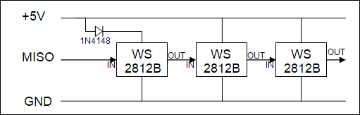
The WS2812B are wired in series, and the control signal is a serial signal: The first LED captures the first control word to configure itself, and transmits the following words to the following LEDs, which repeat the operation. So each LED captures the first word it receives and transmits the following ones.
Each command word consists of 24 bits: 8 bits per color, which allows 256 levels per color.
Each control bit on the serial signal is made up of 2 phases: a first phase has a level 1 and a second phase has a level 0. The duration of the first phase codes the value of the bit at 1 or at 0:
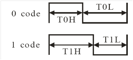
The last command word must be followed by 50 µs at level 0 to indicate the end of the sequence: When a LED in the chain sees the level at 0 for 50 µs, it knows that the next command word is for it.
Timing analysis
The timing to respect for the serial signal is relatively precise:
| Bit period | 1250±150ns | 1100ns < TxH+TxL < 1400ns |
| High pulse for 0 (T0H) | 400±150ns | 250 < T0H < 550 |
| High pulse for 01(T1H) | 850±150ns | 700 < T1H < 1000 |
WS2812B timing specification
The challenge is to generate this signal:
- Within the time tolerances acceptable by the WS2812B
- By a method usable by an STM32
Note that T1H is approximately twice as long as T0H. And that T1L (i.e. 1250-850 = 400) is equal to T0H. We can therefore consider that each bit is coded by 3 phases of equal durations.
If we choose a bit duration of 1200ns, we deduce that:
T0H = 400ns and T0L = 800ns. So the bit pattern to generate a “0” is “100”
T1H = 800ns and T1L = 400ns. So the bit pattern to generate a “1” is “110”
All of this is perfectly within the tolerances indicated by the specification. Warning: there are several datasheets circulating with different values, and inconsistencies within some of them!
The SPI way
You have to be able to generate this serial signal with good precision (better than 100 µs), so it is out of the question to control a GPIO by program. It is therefore necessary to use a DMA which guarantees better timing. In addition, the amount of memory is limited on MCUs. The encoding of the bits to be transmitted must be as compact as possible. With our coding of 3 phases per bit it is not possible to make it more compact than 3 bits per bit to be transmitted. Consequently, the 24-bit control word for 1 LED is encoded in 72 bits or 9 bytes.
Small sizing study:
For 1000 LEDs, the command word buffer is at least 3000 bytes (3 color components of 1 byte).
Once encoded, the buffer to be transmitted is 9000 bytes. We will see that it is possible to considerably reduce the size of this buffer.
The duration of the control signal for the LED chain is: 1000x24x1.2µs + 50µs = 28850µs. This allows you to consider refreshing all the LEDs 30 times per second.
To transmit these bits serially, what can be better than using a serial device such as SPI!
The duration of a control phase is 0.4µs, and therefore requires an SPI frequency of 2.5 MHz.
The SPI devices of the STM32 unfortunately do not have a baud rate generator, this is a well-known limitation. You can only use a division by a power of 2 of the PCLKx bus frequency. This is itself a division of the CPU frequency.
With a divider of 16 this imposes a bus frequency of 40 MHz, and a divider of 32 imposes a bus frequency of 80 MHz. These frequencies are compatible with the STM32F411 used.
It will therefore be necessary to configure the HCLK clock of the STM32F411 at 80 MHz and the spibasic library will calculate the SPI divider according to the bus on which the SPI used is located.
SPI frequency tolerance
The period of a bit must be between 1.1µs and 1.4µs. This induces an SPI frequency of:
Min: 1 / (1.1 / 3) = 2.7 MHz
Max: 1 / (1.4 / 3) = 2.14 MHz
If you are adventurous you can experiment with periods between 1.1µs and 9µs, to increase the available SPI frequency range (With a period of 6µs, the SPI frequency is 0.5MHz). See the links below.
Hardware realization
Wiring is simple:
- Connect the + of the LEDs to 5V
- Connect the ground of the LEDs to the ground of the assembly
- Connect the MISO pin from the SPI to the IN pin of the 1st LED. The other SPI pins are not used.
There is, however, a difficulty. The IN pin expects a high signal level of at least 3.5V, which the MISO output cannot provide (3.3V max). So you need a level shifter. There are several solutions:
- Use a dedicated single gate circuit such as MC74VHC1GT86 or SN74LV1T34
- Use a trick already described elsewhere: use a lower power supply for the 1st LED, which lowers the high level threshold
To lower the power supply to the 1st LED just insert a 1N4148 diode between the 5V power supply and the V+ pin of the LED. In this way the LED is supplied with 5-0.7 = 4.3V. And the minimum level for a high signal becomes 4.3×0.7 = 3.01V, which is compatible with an MCU powered by 3.3V.
The 1st LED output high level is 4.3V, which is well above the 3.5V required.
Software realization
In the application the color of an LED is a 32-bit word, with the format 0RGB, one byte per color component.
To transmit a color word by SPI, this 32-bit word must be converted into 9 bytes. In order to do this as quickly as possible, a pre-calculated transcoding table is used. It converts a color component byte to 3 bytes. By accessing the table 3 times, each R, G and B component can be converted into 9 bytes that can be transmitted by SPI.
// The wsTrancode table allows to transcode a 1 byte color to 3 byte SPI
// So the table has 256 entry of 3 bytes

const uint8_t	wsTrancode [256*3] =
{
	0x92, 0x49, 0x24,	//   0
	0x92, 0x49, 0x26,	//   1
	0x92, 0x49, 0x34,	//   2
	0x92, 0x49, 0x36,	//   3
	0x92, 0x49, 0xA4,	//   4
	0x92, 0x49, 0xA6,	//   5
	0x92, 0x49, 0xB4,	//   6
	0x92, 0x49, 0xB6,	//   7
	0x92, 0x4D, 0x24,	//   8
	0x92, 0x4D, 0x26,	//   9
	0x92, 0x4D, 0x34,	//  10
	0x92, 0x4D, 0x36,	//  11
	0x92, 0x4D, 0xA4,	//  12
	0x92, 0x4D, 0xA6,	//  13
	0x92, 0x4D, 0xB4,	//  14
	0x92, 0x4D, 0xB6,	//  15
	0x92, 0x69, 0x24,	//  16
	0x92, 0x69, 0x26,	//  17
	0x92, 0x69, 0x34,	//  18
	0x92, 0x69, 0x36,	//  19
	0x92, 0x69, 0xA4,	//  20
	0x92, 0x69, 0xA6,	//  21
	0x92, 0x69, 0xB4,	//  22
	0x92, 0x69, 0xB6,	//  23
	0x92, 0x6D, 0x24,	//  24
	0x92, 0x6D, 0x26,	//  25
	0x92, 0x6D, 0x34,	//  26
	0x92, 0x6D, 0x36,	//  27
	0x92, 0x6D, 0xA4,	//  28
	0x92, 0x6D, 0xA6,	//  29
	0x92, 0x6D, 0xB4,	//  30
	0x92, 0x6D, 0xB6,	//  31
	0x93, 0x49, 0x24,	//  32
	0x93, 0x49, 0x26,	//  33
	0x93, 0x49, 0x34,	//  34
	0x93, 0x49, 0x36,	//  35
	0x93, 0x49, 0xA4,	//  36
	0x93, 0x49, 0xA6,	//  37
	0x93, 0x49, 0xB4,	//  38
	0x93, 0x49, 0xB6,	//  39
	0x93, 0x4D, 0x24,	//  40
	0x93, 0x4D, 0x26,	//  41
	0x93, 0x4D, 0x34,	//  42
	0x93, 0x4D, 0x36,	//  43
	0x93, 0x4D, 0xA4,	//  44
	0x93, 0x4D, 0xA6,	//  45
	0x93, 0x4D, 0xB4,	//  46
	0x93, 0x4D, 0xB6,	//  47
	0x93, 0x69, 0x24,	//  48
	0x93, 0x69, 0x26,	//  49
	0x93, 0x69, 0x34,	//  50
	0x93, 0x69, 0x36,	//  51
	0x93, 0x69, 0xA4,	//  52
	0x93, 0x69, 0xA6,	//  53
	0x93, 0x69, 0xB4,	//  54
	0x93, 0x69, 0xB6,	//  55
	0x93, 0x6D, 0x24,	//  56
	0x93, 0x6D, 0x26,	//  57
	0x93, 0x6D, 0x34,	//  58
	0x93, 0x6D, 0x36,	//  59
	0x93, 0x6D, 0xA4,	//  60
	0x93, 0x6D, 0xA6,	//  61
	0x93, 0x6D, 0xB4,	//  62
	0x93, 0x6D, 0xB6,	//  63
	0x9A, 0x49, 0x24,	//  64
	0x9A, 0x49, 0x26,	//  65
	0x9A, 0x49, 0x34,	//  66
	0x9A, 0x49, 0x36,	//  67
	0x9A, 0x49, 0xA4,	//  68
	0x9A, 0x49, 0xA6,	//  69
	0x9A, 0x49, 0xB4,	//  70
	0x9A, 0x49, 0xB6,	//  71
	0x9A, 0x4D, 0x24,	//  72
	0x9A, 0x4D, 0x26,	//  73
	0x9A, 0x4D, 0x34,	//  74
	0x9A, 0x4D, 0x36,	//  75
	0x9A, 0x4D, 0xA4,	//  76
	0x9A, 0x4D, 0xA6,	//  77
	0x9A, 0x4D, 0xB4,	//  78
	0x9A, 0x4D, 0xB6,	//  79
	0x9A, 0x69, 0x24,	//  80
	0x9A, 0x69, 0x26,	//  81
	0x9A, 0x69, 0x34,	//  82
	0x9A, 0x69, 0x36,	//  83
	0x9A, 0x69, 0xA4,	//  84
	0x9A, 0x69, 0xA6,	//  85
	0x9A, 0x69, 0xB4,	//  86
	0x9A, 0x69, 0xB6,	//  87
	0x9A, 0x6D, 0x24,	//  88
	0x9A, 0x6D, 0x26,	//  89
	0x9A, 0x6D, 0x34,	//  90
	0x9A, 0x6D, 0x36,	//  91
	0x9A, 0x6D, 0xA4,	//  92
	0x9A, 0x6D, 0xA6,	//  93
	0x9A, 0x6D, 0xB4,	//  94
	0x9A, 0x6D, 0xB6,	//  95
	0x9B, 0x49, 0x24,	//  96
	0x9B, 0x49, 0x26,	//  97
	0x9B, 0x49, 0x34,	//  98
	0x9B, 0x49, 0x36,	//  99
	0x9B, 0x49, 0xA4,	// 100
	0x9B, 0x49, 0xA6,	// 101
	0x9B, 0x49, 0xB4,	// 102
	0x9B, 0x49, 0xB6,	// 103
	0x9B, 0x4D, 0x24,	// 104
	0x9B, 0x4D, 0x26,	// 105
	0x9B, 0x4D, 0x34,	// 106
	0x9B, 0x4D, 0x36,	// 107
	0x9B, 0x4D, 0xA4,	// 108
	0x9B, 0x4D, 0xA6,	// 109
	0x9B, 0x4D, 0xB4,	// 110
	0x9B, 0x4D, 0xB6,	// 111
	0x9B, 0x69, 0x24,	// 112
	0x9B, 0x69, 0x26,	// 113
	0x9B, 0x69, 0x34,	// 114
	0x9B, 0x69, 0x36,	// 115
	0x9B, 0x69, 0xA4,	// 116
	0x9B, 0x69, 0xA6,	// 117
	0x9B, 0x69, 0xB4,	// 118
	0x9B, 0x69, 0xB6,	// 119
	0x9B, 0x6D, 0x24,	// 120
	0x9B, 0x6D, 0x26,	// 121
	0x9B, 0x6D, 0x34,	// 122
	0x9B, 0x6D, 0x36,	// 123
	0x9B, 0x6D, 0xA4,	// 124
	0x9B, 0x6D, 0xA6,	// 125
	0x9B, 0x6D, 0xB4,	// 126
	0x9B, 0x6D, 0xB6,	// 127
	0xD2, 0x49, 0x24,	// 128
	0xD2, 0x49, 0x26,	// 129
	0xD2, 0x49, 0x34,	// 130
	0xD2, 0x49, 0x36,	// 131
	0xD2, 0x49, 0xA4,	// 132
	0xD2, 0x49, 0xA6,	// 133
	0xD2, 0x49, 0xB4,	// 134
	0xD2, 0x49, 0xB6,	// 135
	0xD2, 0x4D, 0x24,	// 136
	0xD2, 0x4D, 0x26,	// 137
	0xD2, 0x4D, 0x34,	// 138
	0xD2, 0x4D, 0x36,	// 139
	0xD2, 0x4D, 0xA4,	// 140
	0xD2, 0x4D, 0xA6,	// 141
	0xD2, 0x4D, 0xB4,	// 142
	0xD2, 0x4D, 0xB6,	// 143
	0xD2, 0x69, 0x24,	// 144
	0xD2, 0x69, 0x26,	// 145
	0xD2, 0x69, 0x34,	// 146
	0xD2, 0x69, 0x36,	// 147
	0xD2, 0x69, 0xA4,	// 148
	0xD2, 0x69, 0xA6,	// 149
	0xD2, 0x69, 0xB4,	// 150
	0xD2, 0x69, 0xB6,	// 151
	0xD2, 0x6D, 0x24,	// 152
	0xD2, 0x6D, 0x26,	// 153
	0xD2, 0x6D, 0x34,	// 154
	0xD2, 0x6D, 0x36,	// 155
	0xD2, 0x6D, 0xA4,	// 156
	0xD2, 0x6D, 0xA6,	// 157
	0xD2, 0x6D, 0xB4,	// 158
	0xD2, 0x6D, 0xB6,	// 159
	0xD3, 0x49, 0x24,	// 160
	0xD3, 0x49, 0x26,	// 161
	0xD3, 0x49, 0x34,	// 162
	0xD3, 0x49, 0x36,	// 163
	0xD3, 0x49, 0xA4,	// 164
	0xD3, 0x49, 0xA6,	// 165
	0xD3, 0x49, 0xB4,	// 166
	0xD3, 0x49, 0xB6,	// 167
	0xD3, 0x4D, 0x24,	// 168
	0xD3, 0x4D, 0x26,	// 169
	0xD3, 0x4D, 0x34,	// 170
	0xD3, 0x4D, 0x36,	// 171
	0xD3, 0x4D, 0xA4,	// 172
	0xD3, 0x4D, 0xA6,	// 173
	0xD3, 0x4D, 0xB4,	// 174
	0xD3, 0x4D, 0xB6,	// 175
	0xD3, 0x69, 0x24,	// 176
	0xD3, 0x69, 0x26,	// 177
	0xD3, 0x69, 0x34,	// 178
	0xD3, 0x69, 0x36,	// 179
	0xD3, 0x69, 0xA4,	// 180
	0xD3, 0x69, 0xA6,	// 181
	0xD3, 0x69, 0xB4,	// 182
	0xD3, 0x69, 0xB6,	// 183
	0xD3, 0x6D, 0x24,	// 184
	0xD3, 0x6D, 0x26,	// 185
	0xD3, 0x6D, 0x34,	// 186
	0xD3, 0x6D, 0x36,	// 187
	0xD3, 0x6D, 0xA4,	// 188
	0xD3, 0x6D, 0xA6,	// 189
	0xD3, 0x6D, 0xB4,	// 190
	0xD3, 0x6D, 0xB6,	// 191
	0xDA, 0x49, 0x24,	// 192
	0xDA, 0x49, 0x26,	// 193
	0xDA, 0x49, 0x34,	// 194
	0xDA, 0x49, 0x36,	// 195
	0xDA, 0x49, 0xA4,	// 196
	0xDA, 0x49, 0xA6,	// 197
	0xDA, 0x49, 0xB4,	// 198
	0xDA, 0x49, 0xB6,	// 199
	0xDA, 0x4D, 0x24,	// 200
	0xDA, 0x4D, 0x26,	// 201
	0xDA, 0x4D, 0x34,	// 202
	0xDA, 0x4D, 0x36,	// 203
	0xDA, 0x4D, 0xA4,	// 204
	0xDA, 0x4D, 0xA6,	// 205
	0xDA, 0x4D, 0xB4,	// 206
	0xDA, 0x4D, 0xB6,	// 207
	0xDA, 0x69, 0x24,	// 208
	0xDA, 0x69, 0x26,	// 209
	0xDA, 0x69, 0x34,	// 210
	0xDA, 0x69, 0x36,	// 211
	0xDA, 0x69, 0xA4,	// 212
	0xDA, 0x69, 0xA6,	// 213
	0xDA, 0x69, 0xB4,	// 214
	0xDA, 0x69, 0xB6,	// 215
	0xDA, 0x6D, 0x24,	// 216
	0xDA, 0x6D, 0x26,	// 217
	0xDA, 0x6D, 0x34,	// 218
	0xDA, 0x6D, 0x36,	// 219
	0xDA, 0x6D, 0xA4,	// 220
	0xDA, 0x6D, 0xA6,	// 221
	0xDA, 0x6D, 0xB4,	// 222
	0xDA, 0x6D, 0xB6,	// 223
	0xDB, 0x49, 0x24,	// 224
	0xDB, 0x49, 0x26,	// 225
	0xDB, 0x49, 0x34,	// 226
	0xDB, 0x49, 0x36,	// 227
	0xDB, 0x49, 0xA4,	// 228
	0xDB, 0x49, 0xA6,	// 229
	0xDB, 0x49, 0xB4,	// 230
	0xDB, 0x49, 0xB6,	// 231
	0xDB, 0x4D, 0x24,	// 232
	0xDB, 0x4D, 0x26,	// 233
	0xDB, 0x4D, 0x34,	// 234
	0xDB, 0x4D, 0x36,	// 235
	0xDB, 0x4D, 0xA4,	// 236
	0xDB, 0x4D, 0xA6,	// 237
	0xDB, 0x4D, 0xB4,	// 238
	0xDB, 0x4D, 0xB6,	// 239
	0xDB, 0x69, 0x24,	// 240
	0xDB, 0x69, 0x26,	// 241
	0xDB, 0x69, 0x34,	// 242
	0xDB, 0x69, 0x36,	// 243
	0xDB, 0x69, 0xA4,	// 244
	0xDB, 0x69, 0xA6,	// 245
	0xDB, 0x69, 0xB4,	// 246
	0xDB, 0x69, 0xB6,	// 247
	0xDB, 0x6D, 0x24,	// 248
	0xDB, 0x6D, 0x26,	// 249
	0xDB, 0x6D, 0x34,	// 250
	0xDB, 0x6D, 0x36,	// 251
	0xDB, 0x6D, 0xA4,	// 252
	0xDB, 0x6D, 0xA6,	// 253
	0xDB, 0x6D, 0xB4,	// 254
	0xDB, 0x6D, 0xB6 	// 255
} ;
You need a function to transcode a color buffer to a buffer that can feed the SPI by DMA:
//	Generate a buffer to send on SPI MOSI
//	Input pixel are in 0RGB order
//	Output buffer for SPI is in GRB order: 3 bytes per color, 9 bytes per pixel  |G7-G0|R7-R0|B7-B0|
//	nb is the count of pixels in pPixel

uint32_t	wsGenerateBuffer (const uint32_t * pPixel, uint8_t * pBuffer, uint32_t nb)
{
	uint32_t		ii ;
	uint32_t		color ;
	const uint8_t	* pTable ;

	for (ii = 0u ; ii < nb ; ii++)
	{
		// Generate Green
		color = ((* pPixel) >> 8u) & 0xFFu ;
		pTable = wsTrancode + (color * 3u) ;
		* pBuffer++ = * pTable++ ;
		* pBuffer++ = * pTable++ ;
		* pBuffer++ = * pTable++ ;

		// Generate Red
		color = ((* pPixel) >> 16u) & 0xFFu ;
		pTable = wsTrancode + (color * 3u) ;
		* pBuffer++ = * pTable++ ;
		* pBuffer++ = * pTable++ ;
		* pBuffer++ = * pTable++ ;

		// Generate Blue
		color = (* pPixel) & 0xFFu ;
		pTable = wsTrancode + (color * 3u) ;
		* pBuffer++ = * pTable++ ;
		* pBuffer++ = * pTable++ ;
		* pBuffer++ = * pTable++ ;

		pPixel++ ;
	}

	// Add 6 0 byte to reset the transmit (~57 us)
	* pBuffer++ = 0 ;
	* pBuffer++ = 0 ;
	* pBuffer++ = 0 ;
	* pBuffer++ = 0 ;
	* pBuffer++ = 0 ;
	* pBuffer++ = 0 ;

	return (nb * 9u) + 6u ;		// Count of bytes in pBuffer
}
We need some functions and data to manage the SPI. First, we need a SPI descriptor which will configure the SPI and the DMA transmission. Since the receiver is not used, the receive DMA is not configured.
//------------------------------------------------------------------
//	We want a SPI baud rate of 2.5 MHz.
//	=> CPU speed need to be 2.5 * 16 = 40 MHz, or 2.5 * 32 = 80 MHz
//	Use only MOSI pin

#define	SPI_BAUDRATE	2500000

static	const spiDesc_t	wsSpiDesc =
{
	10,								// id
	RCC_APB2ENR_SPI1EN_Pos,			// SPI periph pos
	SPI1,							// Pointer to SPI registers
	{	'A',	7,	AA_GPIO_AF_5,	AA_GPIO_MODE_ALT_PP | AA_GPIO_SPEED_LOW   },		// MOSI
	{	'0',	6,	AA_GPIO_AF_5,	AA_GPIO_MODE_ALT_PP | AA_GPIO_SPEED_LOW   },		// MISO
	{	'0',	5,	AA_GPIO_AF_5,	AA_GPIO_MODE_ALT_PP | AA_GPIO_SPEED_LOW   },		// SCK
	{	'0',	4,	AA_GPIO_AF_0,	AA_GPIO_MODE_OUTPUT_PP | AA_GPIO_SPEED_MEDIUM },	// NSS select USER/SOFT
	{	// DMA Tx
		2,									//	DMA number 1 or 2, 0 => unused descriptor
		DMA_TO_STREAMCHAN (3, 3),			//	DMA_TO_STREAMCHAN (stream number 0..7, channel number 0..7)
		SPI_DMA_INT_PRIORITY,				//	DMA Interrupt priority
		LL_DMA_DIRECTION_MEMORY_TO_PERIPH |	//	Direction, e.g. LL_DMA_DIRECTION_PERIPH_TO_MEMORY
		LL_DMA_MODE_NORMAL                |	//	Mode
		LL_DMA_PRIORITY_HIGH,				//	DMA priority
	},
	{	// DMA Rx
		0,									//	DMA number 1 or 2, 0 => unused descriptor
		DMA_TO_STREAMCHAN (2, 3),			//	DMA_TO_STREAMCHAN (stream number 0..7, channel number 0..7)
		SPI_DMA_INT_PRIORITY,				//	DMA Interrupt priority
		LL_DMA_DIRECTION_PERIPH_TO_MEMORY |	//	Direction, e.g. LL_DMA_DIRECTION_PERIPH_TO_MEMORY
		LL_DMA_MODE_NORMAL                |	//	Mode
		LL_DMA_PRIORITY_HIGH,				//	DMA priority
	},
} ;

static	spiHandle_t	spiHdl ;				// The master SPI handle returned by spiMasterConfigure()
The SPI functions are simple:
//------------------------------------------------------------------

spiStatus_t	wsSpiConfigure (const spiDesc_t * pSpiDesc)
{
	spiStatus_t			sts ;

	sts = spiMasterConfigure (pSpiDesc, SPI_BAUDRATE, SPI_BITS_8 | SPI_NSS_USER | SPI_DIR_HALF_TX | SPI_MODE_0, & spiHdl) ;
	if (sts != SPI_ENONE)
	{
		aaPrintf ("spiMasterConfigure error: %d\n", sts) ;
	}

	return sts ;
}

//------------------------------------------------------------------
//	Transmit pBuffer on SPI, MSB first

void	wsSpiSend (uint8_t * pBuffer, uint32_t nByte)
{
	(void) spiMasterExchangeDma (spiHdl, pBuffer, NULL, nByte) ;
}

//--------------------------------------------------------------------------------
And now a very simple test which turns on 4 LEDs for 2 seconds and then turns them off:
#define		LED_NB		4
#define		LED_BYTES	9	// Count of DMA byte per LED

// The colors buffers of the LEDs
uint32_t	motif_1   [LED_NB] = { 0x00800000, 0x00008000, 0x00000080, 0x00808000 } ;
uint32_t	motif_Off [LED_NB] = { 0x00000000, 0x00000000, 0x00000000, 0x00000000 } ;

uint8_t		dmaBuffer [LED_NB * LED_BYTES] ;

void	wsTest (void)
{
	uint32_t	nByte ;

	wsSpiConfigure (& wsSpiDesc) ;

	// Build the DMA buffer
	nByte = wsGenerateBuffer (motif_1, dmaBuffer, LED_NB) ;

	// Transmit
	wsSpiSend (dmaBuffer, nByte) ;

	// Wait 2 seconds
	aaTaskDelay (bspGetTickRate () * 2u) ;

	// Turn off the LED
	nByte = wsGenerateBuffer (motif_Off, dmaBuffer, LED_NB) ;
	wsSpiSend (dmaBuffer, nByte) ;
}
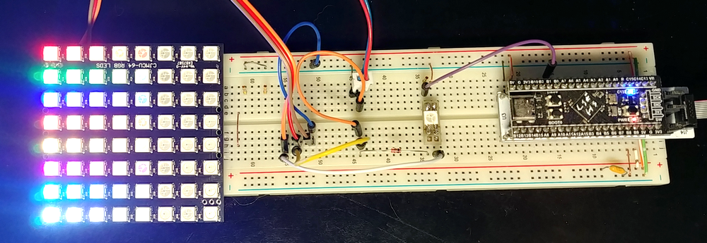
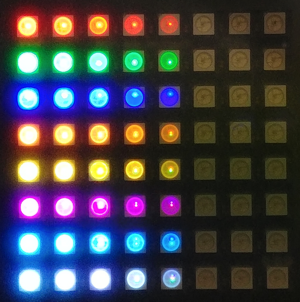
The test bench with the 1st LED, the diode and a 8×8 WS2812B panel:
The color palette (I use only 41 colors for this project):
The wand
I made this wand very quickly (in other words urgently) for a Harry Potter party! It is made of :
- 35 WS2812B strip
- A low cost STM32F411 “BlackPill” module
- A 5000mAh smart phone recharge bank. It provides the necessary 5V and charges as easily as a smart phone
- A box made with a 3D printer. Pretty ugly but no time to refine…
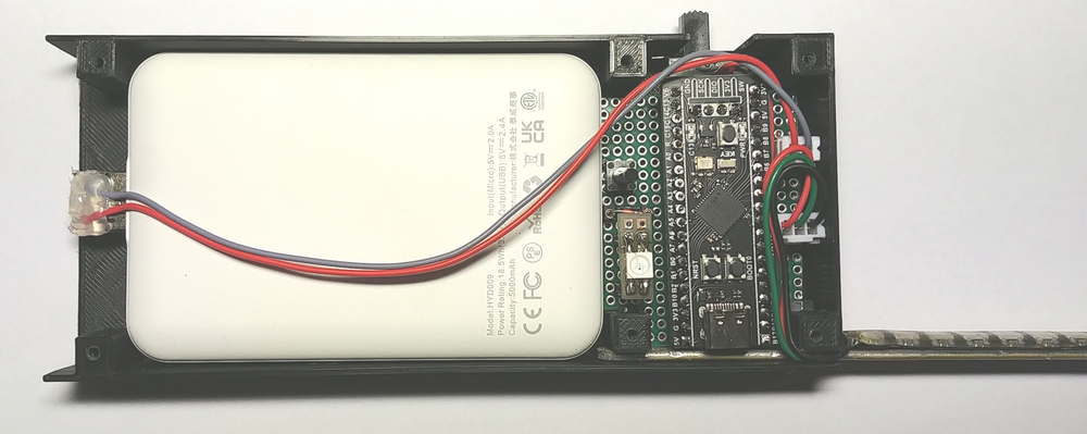
The working wand:
Conclusion
Finally, you need very little code to implement the WS2812B.
But you still have a lot of work to do to get great animations.
Links
Download the source code of the wand with the WS2812B library.
The WS2812B datasheet.
Some experiment on WS2812B timing.
Using more than 3 bits per bit on SPI.
A very clever code to transcode pixels without a precomputed table.
Complements
DMA buffer
When a long string of LEDS is used, the DMA buffer needed to update it all at once can be prohibitively large. For example on an MCU with little RAM such as the STM32G070 with 32KB of RAM.
For a chain of 1000 LEDs you need at least a color buffer of 4000 bytes and a DMA buffer of 9000 bytes. It is sometimes necessary to have a double color buffer for certain animations. In this case, a chain of 1000 LEDs requires 17000 bytes. This is permissible, but if there are 2 channels to manage and update at the same time this is not possible.
The solution is to use DMA in circular mode, which only requires a fraction of the aforementioned DMA buffer. Each time a ½ buffer has been issued by the SPI, the DMA issues an interrupt, and the software can then refill this ½ buffer. What is critical here is the frequency of the interruptions.
If an interruption period of 5ms is chosen this allows the ½ buffer to be sized for 5000 / 28.8 = 174 LEDs (28.8 is the time in µs to emit 24 bits of 1.2µs). The size of the DMA buffer is therefore 174 * 9 * 2 = 3132 bytes. That is 5868 bytes saved!
Number of colors
It turns out that the 16,000,000 colors allowed by the WS2812B are not visually differentiable. It is quite possible to limit the number of colors to 65536 for example, without penalizing the visual effects.
In this case, a color is encoded on 16 bits in RGB565 format. In this case less resources are used:
- The FLASH transcoding table requires only 64 entries. To transcode R and B you have to shift the value one bit to the left
- Color buffer in RAM is halved
However, the DMA buffer obviously keeps the same size.
A variant may be easier to use and allows 32768 colors is the RGB555 format. The most significant bit is unused and all color components have the same 5-bit size.
Use a PWM output instead of a SPI MISO
There are examples on the net that use a timer and a PWM output to generate the WS2812B control signal. It turns out that for this the DMA buffer uses 24 words (of 2 or 4 bytes depending on the timer used) for each LED, or 48 to 96 bytes per LED. It’s much more than with the SPI: 9 bytes.
In addition, these examples use a ½ DMA buffer with 1 LED. The interruption period is therefore approximately 30µs. It’s very high.
On the other hand, there is no longer any constraint on the CPU frequency, because the PWM frequency is fully configurable.