Some time ago I got tired of juggling multiple programming and debugging interfaces for STM32, and each time having to adapt connectors. Because obviously each tool has a different connector. The arrival of the STLINK-V3MINI module could have been a solution. But the global component shortage makes it unavailable. So I decided to make my own programming / debug interface.
How to program an STM32?
There are several tools for programming an STM32:
- Chinese STLINK-V2 module. Very low cost, but lacks the VCP which appeared with the STLINK V2-1, and the SWO. We can therefore consider that this module is obsolete.
- There are NUCLEO-64 boards with a STLINK V2-1 and jumpers to isolate the local target, and use an external target. This is the solution I used for a long time, but the format is not practical to recover SWC, SWD, SWO, VCP, GND and 3.3V on the various connectors of the board.
Warning: Recent NUCLEO boards with an STLINK V3 have lost this ability to connect to an external target.
- STLINK V3MINIE. Latest version of STLINK very powerful and available in different module formats. But not very practical to use by a lobbyist:
- Difficult connectors: they are not at 0.1” pitch or are on the edge of the board
- Does not supply 3.3V power to the target. This complicates small quick manipulations: you need a 3.3V power supply and an extra cable.
- And especially out of stock everywhere in the world.
On the other hand, if you are using a supply voltage other than 3.3V on your target board, this is probably the best solution. Indeed, instead of supplying a voltage of 3.3V, this module accepts a reference voltage which it uses to adapt its I/O to the target voltage.
- Segger’s J-LINK. Professional and powerful tool, a bit expensive when you are no longer a student.
In this probe, the VCP is missing, and it provides 5V instead of 3.3V (which is impractical with the STM32…).
My solution
It should be noted that all the solutions above have different connectors, with different functionalities: some have no VCP, others no power supply… And all have a different number of pins.
The specifications for my realization are as follows:
- Use an official STLINK module so that it is compatible with STM tools, and can be updated by these tools.
- Define my own connector pin-out with all the useful features, and the lowest number of pins. I use 10 points.
- Use a standard 0.1’’ (2.54mm) connector. For small boards I also use a 0.05” (1.27mm) connector.
- Provide the target with the 3.3V generated by the STLINK.
- In the event that the 3.3V intensity of the STLINK is insufficient, be able to connect a 5V power supply (a phone/tablet charger for example) and therefore have a 5V -> 3.3V converter
The core
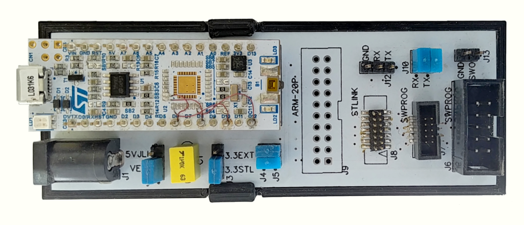
Evaluation boards supplied by STM such as NUCLEO boards have an STLINK interface. The idea is to reuse one of these interfaces. I therefore use as the core of the realization the cheapest NUCLEO-32 board that I found: the NUCLEO-L031K6.
This board has an STM32L031 but above all an STM32F103 dedicated to STLINK V2-1.
On such a small board there are no jumpers to isolate the STLINK part and use it to access an external target. So you have to modify it:
- Unsolder the STM32L031
- Add 3 wires to connect SWC, SWD and VCP-RX to external pins (VCP_TX is already available on CN4-5).
23 PA13 -> CN3-9
24 PA14 -> CN3-11
25 PA15 -> CN3-13
Note: SWO is not available on Cortex-M0(+), so there is no wire routed to F103 pin PA10 (The SWO input of the STLINK). I didn’t add a wire to the NUCLEO for the SWO because I don’t use it from the IDE, I prefer to use a faster dedicated FTDI converter, at 8 or 12 M Bits/s.
This is probably a mistake, if there is a next version I would route the SWO to the F103.
The base
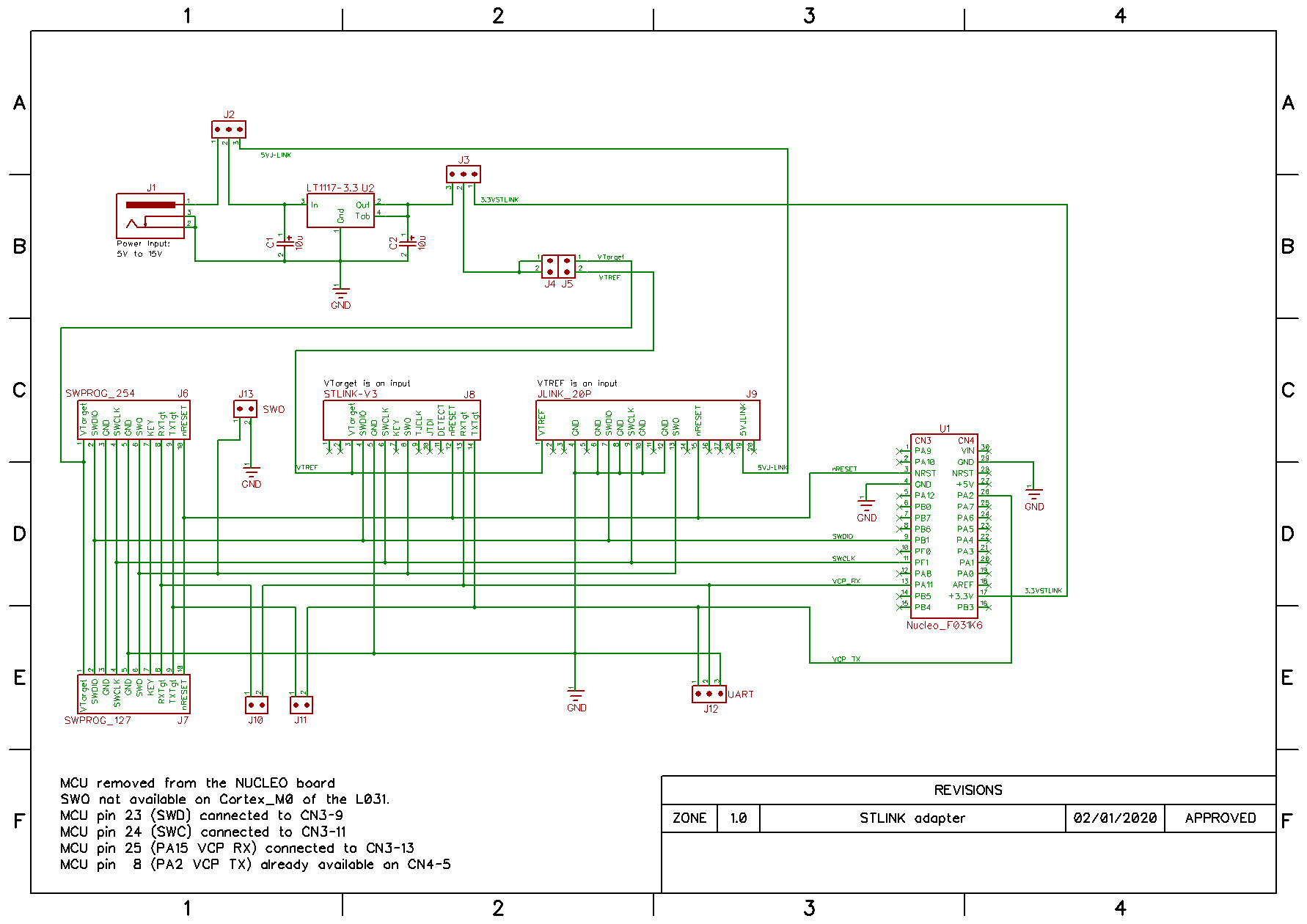
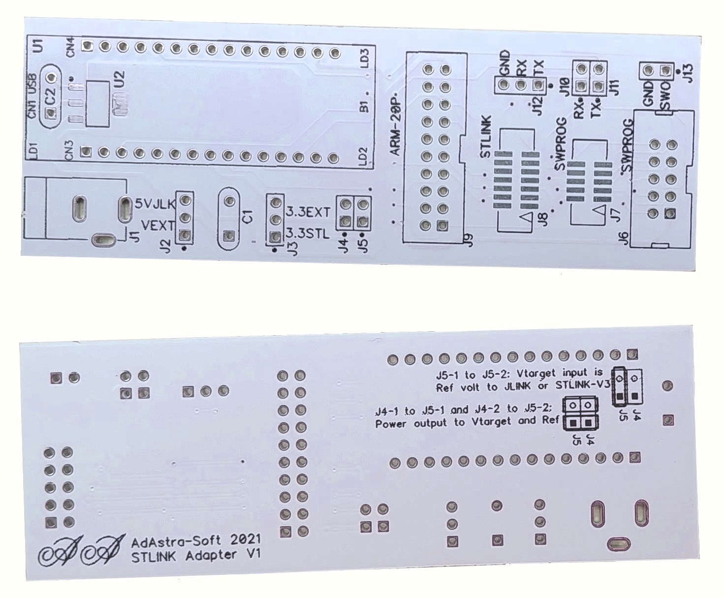
The various elements are grouped together on a printed circuit, with various configuration jumpers:
- The modified NUCLEO module
- The 2.54mm and 1.27mm connectors to the target.
- A 5V -> 3.3V type 1117 converter (800mA) and its 5/2.1mm connector.
- Jumpers to select the 3.3V source to send to the target: STLINK or external.
- A connector to retrieve the SWO on an additional FTDI.
- Jumpers to disconnect the VCP from the target of the STLINK, and to be able to recover it on another connector.
- A jumper to cut off the 3.3V output if the target has an autonomous power supply. On the other hand, some people never use the 3.3V of the probe to avoid potential power conflicts.
This gives the following diagram:
To avoid short circuits, a small box was made with a 3D printer:

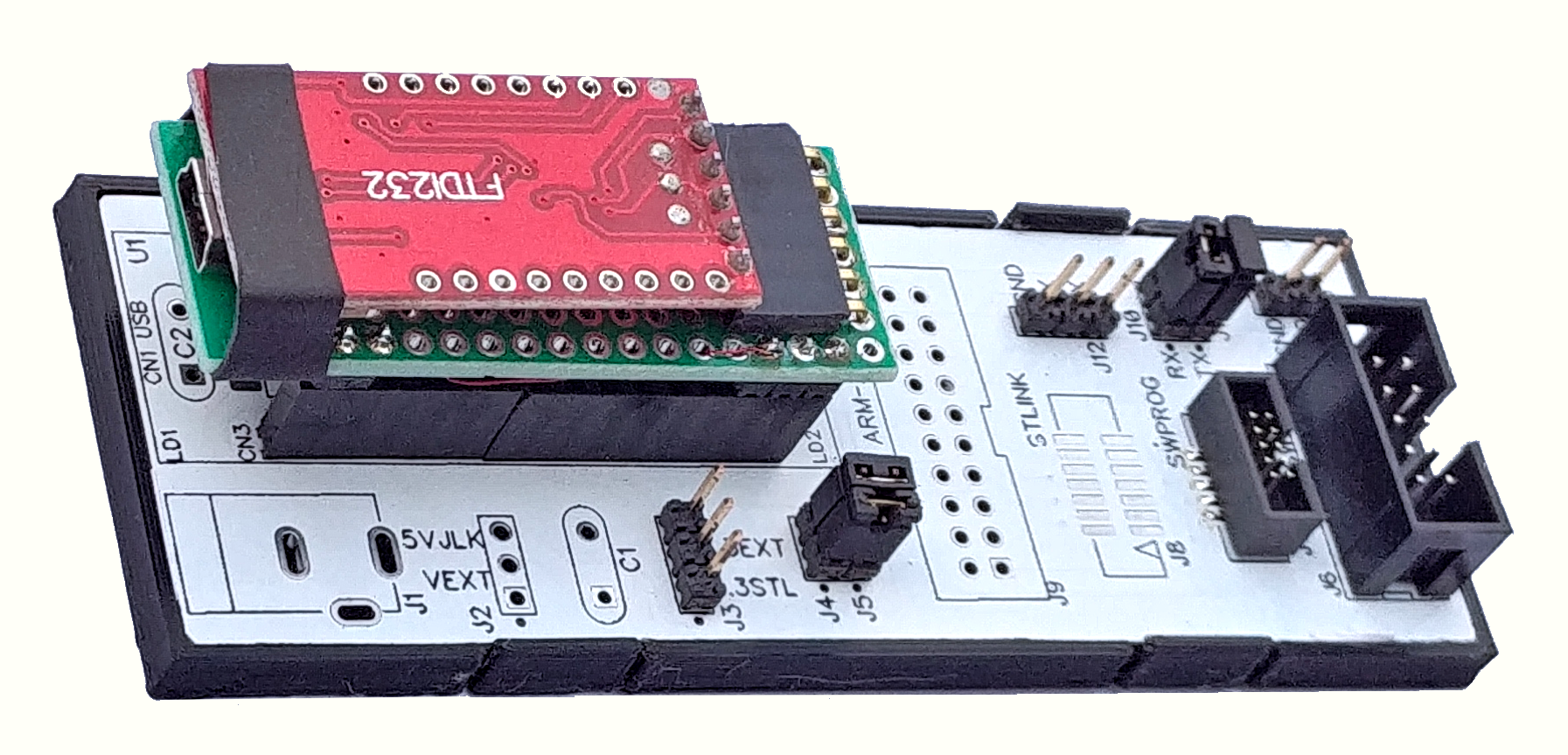
Variant with VCP only
Sometimes it is useful to connect to the target just to use the VCP. This is the case, for example, when you are developing a system with several MCUs and you do not have enough probes.
The solution is to use the base already made, and to replace the NUCLEO board with a cheap FTDI module. This has been done here:
Example of use
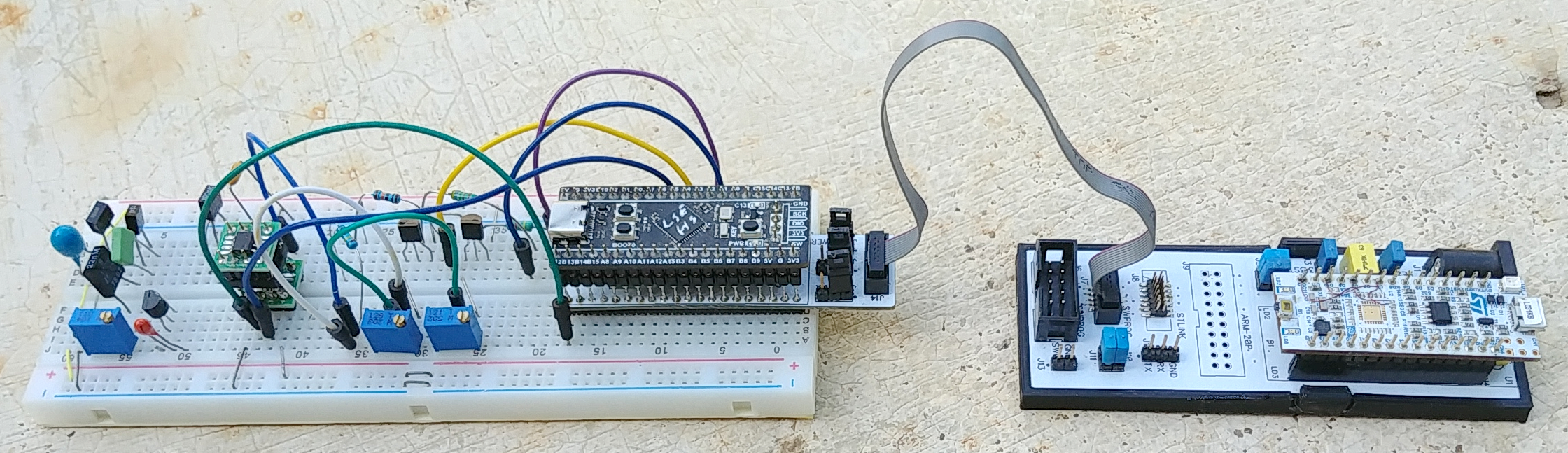
I often use the BlackPill board for rapid developments. To be able to use it on a bread board in connection with the STLINK module, I made a small circuit.

Here it is in real condition:
Conclusion
Since I made this module, I no longer have any connection problems. I was able to program/debug all my boards easily.
The convenience of standardized connectivity and a single tool is a real plus.
I’ve never used the ARM-20P and STLINKV3 connectors, so I don’t know if they work (that’s why I don’t talk about them here).