Here is how I made my multi-channel solar diverter which I named AASun.
Why a solar diverter?
A solar installation can be used in “Self-Consumption”, meaning that the electricity produced is used locally by the producer rather than being sold. Without specialized equipment, consumption is uncertain:
- Part of the production is used for the daily consumption of the home: refrigerator, controlled ventilation, central heating circulator, etc.
- At certain times, several pieces of equipment can begin to consume at the same time and the total of their consumption exceeds the photovoltaic production.
- At other times there are few consumers and the surplus photovoltaic production is injected into the public network (without payment).
To best manage the photovoltaic electricity produced, we can use an energy diverter. This diverter will direct the available energy to several devices based on measurements of consumed and produced energy , the environment (temperature sensors, thermostat contact, time, etc.), and rules defined by the user.
After installing a few solar panels, I decided to make my solar diverter based on an STM32G071CB. The genesis of this diverter, its configuration and its use are explained in the document Doc/AASun.pdf
Main characteristics :
- 10 x 10 cm printed circuit board.
- Designed to be placed on a DIN rail support.
- STM32G071CB microcontroller and 8 MB W25Q64 external flash.
- 1.3” OLED display and 2 buttons to navigate the pages (the 0.96” display is also managed).
- Wired network interface or WIFI interface. Only one of the two can be present on the diverter.
- HTTP server for monitoring, diverter configuration and routing/forcing rules, displaying history.
- 1 to 3 current transformers (CTs) inputs.
- The CT shielding can be connected to earth.
- One of the CTs can be replaced by a Hall effect sensor, for measuring a continuous current (CT can only measure sinus current).
- A nominal continuous voltage measurement input of 12, 24 or 48V, to manage the charging/discharging of a battery.
- 2 PWM routing outputs for external solid state relays (SSRs).
- An auxiliary logic output that can control a mechanical or static relay.
- 1 230V 3A relay on the board.
- 2 logic inputs compatible with 3.3V and 5V (thermostat, push button, hour contact, etc.).
- 2 pulse counting inputs (up to 30V). If these inputs are not used for counting, they can be used as logic inputs.
- 8 green LEDs to display the status of the 4 inputs and 4 outputs.
- A 5V presence LED (yellow), an operating LED (blue).
- 4 DS18B20 temperature sensors.
- 2 routing rules for PWM outputs.
- 8 forcings, each with a start rule and a stop rule that can control the 4 diverter outputs.
- Priority management of routings and forcings.
- Several forcing modes: PWM, standard, burst.
- Daily energy history over 31 days. Power history averaged per ¼ hour over 31 days. The values taken into account are: CT1 to CT3 (CT1 separates import and export), estimated routing of PWM outputs 1 and 2, pulse counters 1 and 2.
- Anti-legionella management.
- Linky interface.
- Console interface by UART or Telnet (wired network or WIFI).
- HT396 easily removable connector for all I/O.
- 5mm removable connector for connection to the main, with earth.
- A ZMPT101B or DL-PT202D transformer for measuring the main voltage.
- Power supply integrated by HLK-PM01 module with common mode choke and filter capacitor, protected by a resettable fuse.
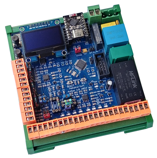
The diverter currently comes in the form of a single board suitable for DIN case:
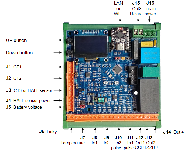
The view above shows the final diverter that implements all of the planned functionality.
The project is available on Github with source code, schematics and documentation.
The project of the prototype is also available on Github. Its documentation explains in more detail the technical choices made during the design of the diverter.
On Github the project is documented in French because it was designed according to the characteristics of the Linky meter which is specifically French. The diverter can, however, be used directly on any 50Hz electrical network.
The source code is commented in English.