This post will show how I use a STLINK-V3MODS from STMicroelectronics to program and debug STM32 MCUs.
In 2020 I designed my own STLINK probe to program and debug STM32 MCUs. It works very well and has provided great service. It is described here.
Since then the situation has changed, since the STLINK-V3MODS appeared, and it is now available!
This module provided by STMicroelectronics is designed to be soldered onto a target board. In my case, not all motherboards need such a resource, and I prefer to create a reusable module.
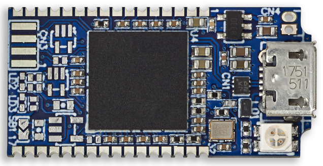
The STLINK-V3MODS
https://www.st.com/en/development-tools/stlink-v3mods.html
This module has multiple functionalities. In addition to the classic SWD, VCP and SWO functions, it can serve as a bridge between USB and the various MCU peripherals: UART, SPI, I2C, CAN, GPIO.
Another advantage of the module is that it provides a power source: 5V and 200mA max. This is a big advantage because you can program/debug small targets with a single connection.
There are a few details to know:
- The module has a T_VCC input which is a voltage supplied by the target to the STLINK-V3MODS module. This allows the module to adapt the voltage of its I/O, but only over the restricted range of 3.0 to 3.6V.
- The pins used by the UART VCP link are named T_VCP_TX and T_VCP_RX: Their name refers to the signals from the target, not from the STLINK module. The T_VCP_TX pin corresponds to the RX of the module, and T_VCP_RX corresponds to the TX of the module.
My probe module specifications
The previous probe module having given complete satisfaction, I am renewing the main functionalities:
- Maintain my “standard” 10-point connector in 0.1’’ and 0.05’’.
- Add LEDs to the RX and TX signals of the VCP to visualize traffic.
- Convert 5V to 3.3V to power the target.
- An independent connector to provide 3.3V and 5V (200 mA max total).
- An independent connector with SWO and GND to be able to use an independent USB bridge.
- Jumpers to be able to isolate some signals between the target and the STLINK-V3MODS:
- RX and TX from the VCP
- SWO
- 3.3V. To be able to use a target that is not 3.3V, or use a target that has its own power supply. The T_VCC signal is connected to VTarget. This jumper therefore makes it possible to isolate T_VCC and VTarget from the 3.3V generated by the board.
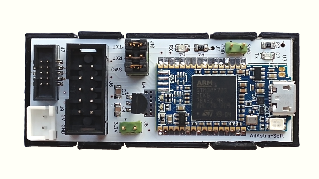
The prototype
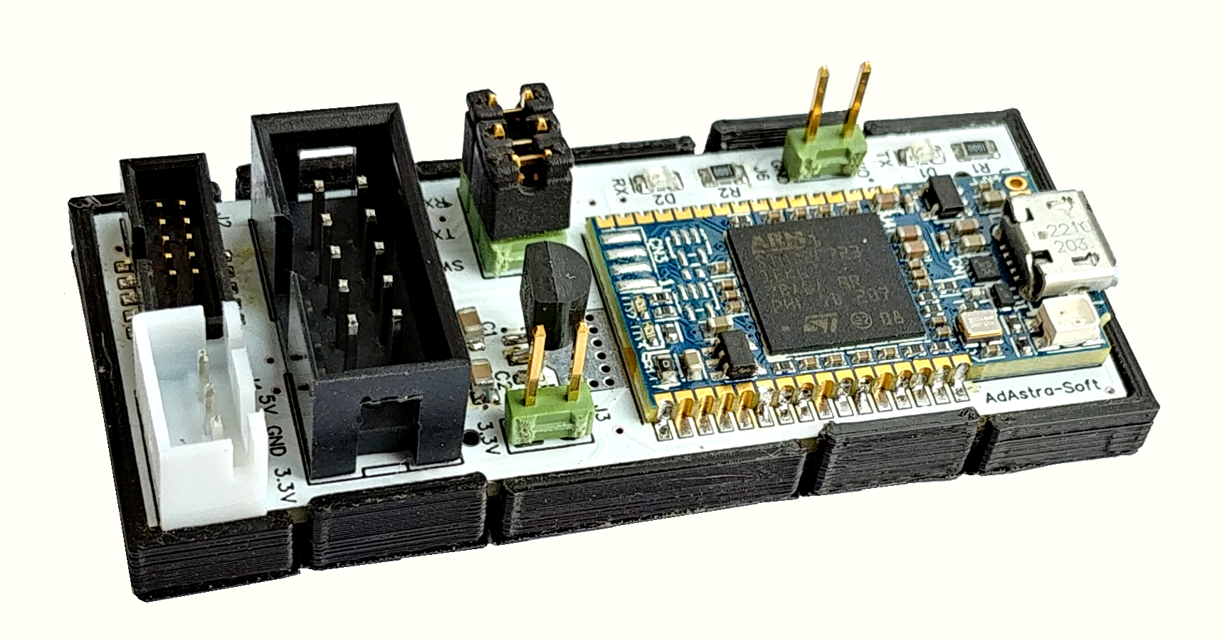
This V1.1 prototype uses a MCP1702 circuit, package is TO-92 instead of SOT-89.
A shell was made with a 3D printer to avoid short circuits with the bottom side.
Download the design files
Download the design files here
Conclusion
Compared to the previous version, this programming/debug probe has the following advantages:
- Smaller
- Cheaper
- More up to date: Uses STLINK-V3 with an STM32F723 MCU which will support future developments.
- Still practical with my standard 10-point connectors and a 3.3V 200mA power supply. Features that a STLINK-V3MINI module that could have been a competitor does not have.
Cordial saludo amigo. Quiero hacer este módulo para poner un STLink-V3mods. Puede compartir tu diseño conmigo, gracias. fredyccori@gmail.com
All the design files can be downloaded from this post.