During the debug phase of a program it is important to have a display of the real-time kernel or application traces. If a standard output device is used such as a UART these traces are very intrusive:
- If the UART is managed under interruption, the frequency of interruptions can be significant: at 19,200 bauds, there are 1,920 interruptions / s and at 115,200 bauds there are 11,520 / s (every 86 µs!).
- If the UART is managed by polling to avoid interruptions, the timing of the application is even more disturbed by the waiting time for the transmission of characters. And even more if the UART does not have a FIFO.
In order not to disturb the behavior of the application under development, the ideal would therefore be to have a communication channel much less intrusive than a UART, USB or Ethernet…
What is SWO
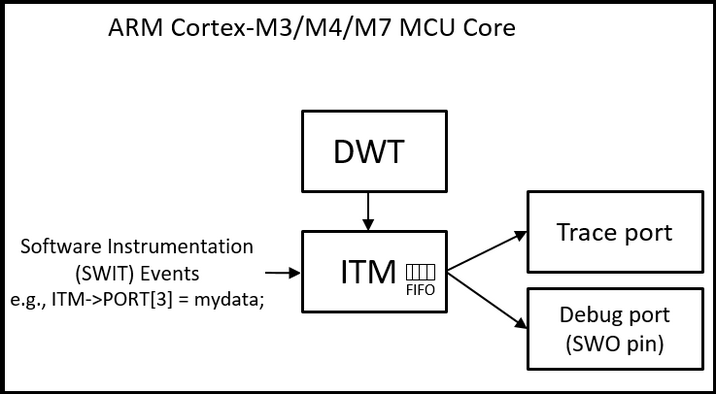
The SWO (Single Wire Output) trace port is an interesting hardware feature of ARM Cortex-M, a part of the CoreSight Debug block. It can be used for several purposes, here we will only talk about the issuance of ASCII traces.
As the name suggests, it only uses one pin of the MCU.
The SWO transmits data packets preceded by a header character. It is possible to send packets of one byte, two bytes (a 16-bit word) or four bytes (a 32-bit word). In our case, a package is therefore made up of 2, 3 or 5 characters.
Up to 32 channels (called “stimulus ports” by ARM) can be used.
The encoding on the output can be of the UART or Manchester type. We will use UART type encoding.
The appropriate probe
The SWO output can operate at a very high speed. The problem is to have a probe capable of receiving this signal, and to transfer it in a practical way to a PC.
Fortunately, FTDI offers the C232HM interface: USB 2.0 Hi-Speed to MPSSE Cable.
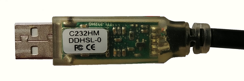
This allows for around 25 € to have a 12 Mbits UART interface on the microcontroller side, and a standard USB interface on the PC side. Using an application such as Putty on the PC side, it is possible to display ASCII traces emitted by the microcontroller at high speed.
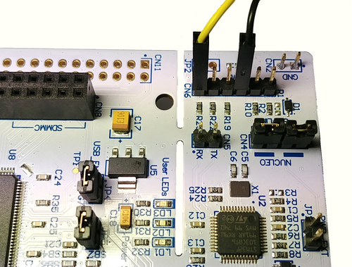
With a STM32 Nucleo board and 2 USB connections to a PC it is possible to have a complete development configuration:
- Atollic TrueSTUDIO or Eclipse + OpenOCD to compile, flash and debug, using the ST-LINK probe included in the Nucleo board.
- Use the virtual COM of the ST-LINK probe of the Nucleo board to have a console for the standard output of the kernel.
- Use SWO and C232HM to capture the debug traces.
At 12 M baud, transmitting packets of 1 character takes 1.7 µs (1 header + 1 character) when the FIFO is full, which is not very intrusive (if the FIFO is empty it is even faster!). This is enough not to disturb the timing of the application in most cases.
On Nucleo boards the SWO output is on pin 6 of the CN6 connector (to connect the yellow wire) and the ground is on pin 3 (to connect the black wire).
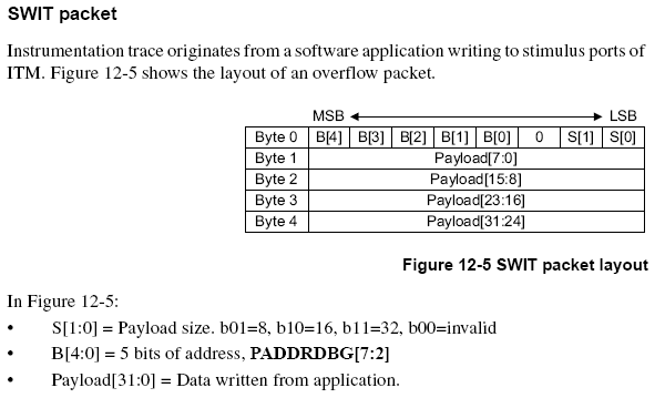
The packet format
The packet header is automatically inserted. It indicates the useful length of the packet and the number of the stimulus port which sent it.
Luckily if we use the “stimulus port” 0 the header of each packet is a non-printable character less than 0x04. Therefore by sending the packets to a terminal the headers are not displayed, and only the trace characters are visible.
Some commercial applications use stimulus 0 for ASCII display in a console, and another for more technical trace information. Sorting is done by using the packet header.
The implementation
To be able to use the SWO output, you must initialize the ITM component of the ARM. For example on an STM32F4xx, this is done with the following code:
/*
	Initialize the SWO trace port for debug message printing
	portMask : Port bit mask to be configured
	cpuCoreFreqHz : CPU core clock frequency in Hz
	baudrate : SWO frequency in Hz
*/

static	uint32_t	bItmAvailable ;

void swoInit (uint32_t portMask, uint32_t cpuCoreFreqHz, uint32_t baudrate)
{
	uint32_t SWOPrescaler = (cpuCoreFreqHz / baudrate) - 1 ;

 	// Debug Exception and Monitor Control Register: enable trace in core debug
	CoreDebug->DEMCR = CoreDebug_DEMCR_TRCENA_Msk;

	// DBGMCU_CR : TRACE_IOEN DBG_STANDBY DBG_STOP 	DBG_SLEEP
	DBGMCU->CR	= 0x00000027;

	// Selected PIN Protocol Register: Select which protocol to use for trace output (2: SWO)
	TPI->SPPR	= 0x00000002 ;

	// Async Clock Prescaler Register: Scale the baud rate of the asynchronous output
	TPI->ACPR	= SWOPrescaler ;

	// ITM Lock Access Register, C5ACCE55 enables more write access to Control Register 0xE00 :: 0xFFC
	ITM->LAR	= 0xC5ACCE55 ;

	// ITM Trace Control Register
	ITM->TCR	= 0x0001000D ;

	// ITM Trace Privilege Register: All stimulus ports
	ITM->TPR	= ITM_TPR_PRIVMASK_Msk ;

	// ITM Trace Enable Register: Enabled tracing on stimulus ports. One bit per stimulus port.
	ITM->TER	= portMask

	// Data Watchpoint and Trace Register
	DWT->CTRL	= 0x400003FE ;

	// Formatter and Flush Control Register
	TPI->FFCR	= 0x00000100 ;

	// ITM/SWO works only if enabled from debugger.
	// If ITM stimulus 0 is not free, don't try to send data to SWO
	if (ITM->PORT [0].u8 == 1)
	{
		bItmAvailable = 1 ;
	}
}
This function must be called only once before using the SWO output.
If the initialization function is called with a baud rate of 12000000, Putty must be configured with the same baud rate when using the virtual COM port of the C232HM.
A link at the bottom of the page gives more precise indications.
To send a character, a 16 or 32 bit word, use:
ITM->PORT[portNo].u8  = value ;	// portNo in the range 0 to 31
ITM->PORT[portNo].u16 = value ;
ITM->PORT[portNo].u32 = value ;
This is a very short code. But before, remember to check that the stimulus port is well initialized, and that the FIFO is not full. This gives the following code, a little simplified, since it is not thread safe.
void swoSend8 (uint8_t value, uint8_t portNo)
{
	if (bItmAvailable != 0)
	{
		while (ITM->PORT [portNo].u8 == 0)
		{
		}
		ITM->PORT[portNo].u8 = value ;
	}
}
The limitations of SWO
- The main one is that it can only be used in conjunction with a debugger, since it is only accessible once the ARM core has gone into debug mode.
- There is no reception channel that would allow it to be used as a console
- Some processors such as Cortex-M0 (+) doesn’t to have this functionality.
Conclusion
With the SWO output, an FTDI C232HM cable and Putty, no need for expensive probe and complex Eclipse plugin to have a complete development configuration and honorable performance.
All this for 25 €, hence the title of this article!
Some links
More information on SWO :
mcuoneclipse.com/2016/10/17/tutorial-using-single-wire-output-swo-with-arm-cortex-m-and-eclipse/
More information on FTDI UART to USB :
PuTTY is an SSH and Telnet client (and also a serial terminal emulator), for the Windows and Linux platforms.
It is very easy to use and easily allows for multiple configurations. In addition, it is very small which is rare these days!
PuTTY doesn’t allows to send CR+LF when the Enter key is pressed. This prevents its use to issue AT commands to devices such as HC-05 or JDY-31.
Luckily someone modified this application and added a setting that allows this functionality, resulting in PuTTY-crlf.
The source code is on github: https://github.com/gniemirowski/putty-crlf
The Windows binary is here: https://www.grzegorz.net/pliki/putty-crlf.zip
Thank you to Grzegorz Niemirowski