
In a real-time system, interrupts are widely used. And the system must respond to these external events in a timely manner. What are the factors affecting these response times, and the means available to optimize them?
Two important definitions regarding interrupts are:
The interrupt latency: it is the interval of time from an external interrupt request signal being raised to the execution of the first instruction of the specific interrupt service routine.
The interrupt jitter: It’s the variation in latency. Often it is qualified by taking the minimum and maximum values of latency (the worst case of latency).
We therefore notice that latency alone is not a sufficient criterion. In practice we want to limit the jitter, while also having the lowest possible latency. For some applications the ideal is to have a zero jitter, with as low a latency as possible.
How to get near zero latency interrupts?
Causes of interrupt latency
The factors affecting the interrupt latency are hardware and software. Some hardware factors include:
- Interrupt controller design. Reaction time is usually very fast (a few ns) and constant.
- Bus occupancy at time of interruption: type of access, DMA…
- The instruction being executed at the time of the interruption. The CPU waits for the end of the instruction before serving the interruption. A move from register to register is very fast, but a multiplication is much longer, and a memory access has no fixed duration depending on the context.
- Interrupt nesting. If the controller allows interrupt nesting, an interruption of a given priority cannot interrupt the service of a higher priority interrupt. We must wait for the end of the high priority ISR, which induces an indefinite delay since it depends on the application.
Among the hardware factors, the latter is the most decisive.
Some software factors.
- The constraints on the interrupt handler introduced by the real-time kernel. In general it is mandatory to call a particular function at the entry of the handler. This introduces a delay before the execution of the handler’s first useful instruction. This generally represents a fraction of µs.
- The implementation of critical sections by the software. If this is done by temporarily inhibiting interruptions, this factor becomes critical.
- The last factor concerns the inhibition of interruptions by libraries or device drivers. This is sometimes uncontrollable if the sources of these software are not available.
The inhibition of interrupts is the determining software factor for interrupt latency.
Implementation of critical sections
Some kernels claim that they never inhibit interrupts. At first glance this is the right solution to control the latency of interrupts. However we must take a closer look.
Often these kernels still inhibit interrupts for very short periods of time to carry out the mandatory atomic operations. The most advanced kernels use special instructions of the CPU to carry out these atomic operations, but the complexity of these instructions makes that their use is rare. These short periods of time while the interrupts are inhibited induces a small interrupt latency jitter.
In order not to inhibit interrupts during critical sections, the scheduler is inhibited. Therefore the processing of an interrupt is done in several steps:
- In the ISR, the minimum processing of the interruption is carried out The rest of the processing is outsourced to a deferred function. In particular the processes which access the kernel variables or which use shared variables with the device handler.
- If the scheduler is not disabled at the time of the interruption, the deferred function is called immediately.
- If the scheduler is disabled at the time of the interruption, a descriptor of the interrupt is inserted in a circular buffer, in order to call the deferred function later.
- When the scheduler is validated again, if the circular buffer of the deferred functions is not empty, these deferred functions are called.
This implementation of critical sections by inhibiting the scheduler introduces complexity, in particular:
- The processing of all interrupts must be split in two. The first ISR instructions are executed with low latency. The delayed function can have a very high latency which cannot be controlled. In particular, it is necessary to manage the case where the same interrupt occurs several times before the scheduler is validated.
- It is necessary to finely estimate the size of the buffer for deferred functions.
The AdAstra-RTK kernel chose to implement critical sections by inhibiting interrupts managed by the kernel. This implementation decision was made because :
- The implementation of the ISR is much simpler.
- The ARM NVIC controller of the Cortex-M architecture allows you to specify the priority level of inhibited interrupts. In other words, it makes it possible to inhibit all interrupts of priority lower than or equal to a certain level, while leaving validated the interrupts of priority higher than this level. Most modern MCUs have this functionality.
So it is possible to segregate two types of interrupts:
- Kernel aware interrupts which can be inhibited during critical sections, but which have access to the kernel API.
- Non kernel aware interrupts or “Zero latency interrupts” which are never inhibited by the kernel. However, these interruptions have constraints on the use of the kernel API. These interrupts must have a higher priority than kernel aware interrupts.
Zero latency interrupts (ZLI)
Interrupts with low latency and very little jitter can be considered. To do this some conditions must be met:
- The interrupt controller must allow interrupt nesting and interrupt prioritization.
- The real-time kernel must segregate interrupts. Higher priority interrupts should never be inhibited by the kernel.
- Device drivers must not globally inhibit interrupts, but use inhibition / validation functions provided by the kernel.
- A single interruption will really be “zero latency”: that of the highest priority. Indeed, this can preempt an interruption of lower priority.
- In the ZLI ISR don’t use the kernel API, except the API specifically designed for this use.
Last remark: the term “zero latency” refers to the software. Hardware latency and jitter are still present.
Zero latency interrupt management with AdAstra-RTK
A ZLI cannot use the kernel API, which is penalizing for communicating with the application. To resolve this, the two-step interrupt processing technique is used:
- In the ZLI ISR the minimal processing is carried out. Then a software interrupt is issued.
- The software interrupt is kernel aware, that is to say that it can be inhibited by the kernel. Its ISR performs the rest of the interrupt processing and can access the kernel API.
This technique is very close to that adopted by the kernels which “never inhibit interrupts”. But it does not require a special buffer for deferred treatments. In addition, the priority of the software interrupt can be chosen as required. It can be the highest priority of kernel aware interrupts if its treatment is urgent.
Practical example
Now let’s see how to actually implement a ZLI. The envisaged application consists of:
- Generate a timer interrupt, this is the ZLI.
- The ZLI ISR increments the interrupt counter, then triggers a software interrupt.
- The software interrupt uses a task signal to activate the task.
- The task can process the data supplied by the ZLI, It displays the value of the interrupt counter.
This example is typical of interrupt handling: The interrupt service routine performs some treatment, and then activates a task.
The declarations :
#include	"aa.h"
#include	"aakernel.h"	// For aaIntEnter()/aaIntExit() in IRQ handler

#include	"timbasic.h"	// To use a timer
#include	"extibasic.h"	// To use a software interrupt

#include	"aaprintf.h"

#define	ZLI_SWI_LINE		0	// The number of the SWI interrupt
#define	ZLI_SIGNAL			1	// The signal to wake up the task

#define	ZLI_FREQ			10	// ZLI frequency
#define	ZLI_TIM_PRIORITY	(BSP_MAX_INT_PRIO-1)	// The lower priority never disabled

// The timer descriptor: TIM4, with output CH1 on PB6
// Choose a timer who doesn't share its IRQ with another device (TIMx, DACx...)
// In timerbasic.h set AA_WITH_TIM4 to 0, to disable this IRQ handler in timbasic.c
static	const	timDesc_t	timInterrupt =
{
	4,							// Descriptor identifier
	4,							// Timer number 1..14
	RCC_APB1RSTR_TIM4RST_Pos,	// RCC_APBxRSTR_TIMnRST_Pos
	RCC_APB1ENR_TIM4EN_Pos,		// RCC_APBxRSTR_TIMnEN_Pos
	TIM_CAP_TYPE_GPT1 | TIM_CAP_CHAN_1_4 | TIM_CAP_UP_DOWN | TIM_CAP_DMA | TIM_CAP_ETR, 	// Capabilities flags
	TIM4,							// Pointer to TIM registers
	TIM4_IRQn,
	{
		{	'B',	6,	AA_GPIO_AF_2,	AA_GPIO_SPEED_HIGH | AA_GPIO_PUSH_PULL | AA_GPIO_PULL_UP },	// Ch1
		{	0,		7,	AA_GPIO_AF_2,	AA_GPIO_SPEED_HIGH | AA_GPIO_PUSH_PULL | AA_GPIO_PULL_UP },	// Ch2
		{	0,		8,	AA_GPIO_AF_2,	AA_GPIO_SPEED_HIGH | AA_GPIO_PUSH_PULL | AA_GPIO_PULL_UP },	// Ch3
		{	0,		9,	AA_GPIO_AF_2,	AA_GPIO_SPEED_HIGH | AA_GPIO_PUSH_PULL | AA_GPIO_PULL_UP },	// Ch4
		{	0,		0,	AA_GPIO_AF_2,	0 },	// Ch1N
		{	0,		0,	AA_GPIO_AF_2,	0 },	// Ch2N
		{	0,		0,	AA_GPIO_AF_2,	0 },	// Ch3N
		{	0,		0,	AA_GPIO_AF_2,	AA_GPIO_SPEED_HIGH | AA_GPIO_PUSH_PULL | AA_GPIO_PULL_UP },	// ETR
		{	0,		0,	AA_GPIO_AF_2,	0 },	// BKIN
	},
} ;

STATIC	uint32_t	zliCounter = 0 ;
STATIC	aaTaskId_t	zliTaskId ;
The ZLI interrupt service routine :
void	TIM4_IRQHandler (void)
{
	// ZLI : No aaIntEnter() / aaIntExit()

	// Increment the counter
	zliCounter ++ ;

	// Triggers the software interrupt
	extiSwiTrigger (ZLI_SWI_LINE) ;
}
The software interrupt service routine :
void EXTI0_IRQHandler (void)
{
	aaIntEnter () ;

	if ((EXTI->PR & EXTI_PR_PR0) != 0)
	{
		// Clear bit
		EXTI->PR = EXTI_PR_PR0 ;
		aaSignalSend (zliTaskId, ZLI_SIGNAL) ;	// Wake up the application task
	}

	aaIntExit () ;
}
The test function :
void	testZli (void)
{
	const timDesc_t	* pTimGen = & timInterrupt ;	// The timer descriptor

	// Configure the timer to generate a frequency on CH1 output
	// and the UPDATE interrupt, that call the ISR
	timTimeBaseInit			(pTimGen, 0, ZLI_FREQ, TIM_INIT_ARR_PRELOADEN) ;
	timConfigureIntr		(pTimGen, ZLI_TIM_PRIORITY, NULL, 0, TIM_INTR_UPDATE) ;
	timOutputChannelEnable	(pTimGen, 1, TIM_OCMODE_PWM1) ;

	// Initialize the SWI interrupt to send the signal
	extiResetInterrupt (ZLI_SWI_LINE) ;
	extiInitSwi (ZLI_SWI_LINE, BSP_IRQPRIOMIN_PLUS(2)) ;

	// Prepare the task to receive the signal
	zliTaskId = aaTaskSelfId () ;
	aaSignalClear (zliTaskId, ZLI_SIGNAL) ;

	timStart (pTimGen) ;

	// Forever loop waiting for the signal from the SWI
	while (1)
	{
		aaSignalWait (ZLI_SIGNAL, NULL, AA_SIGNAL_AND, AA_INFINITE) ;
		aaPrintf (« ZLI count : %d\n », zliCounter) ;
	}
}
That’s all !
The timer is configured to output the frequency signal. This allows you to instrument the code to measure the latency of the timer interrupt. For example, the following function is used to send a pulse to the output BSP_OUTPUT0 defined by the BSP.
void	TIM4_IRQHandler (void)
{
	// ZLI : No aaIntEnter() / aaIntExit()

	bspOutput (BSP_OUTPUT0, 1) ;

	// Increment the counter
	zliCounter ++ ;

	// Triggers the software interrupt
	extiSwiTrigger (ZLI_SWI_LINE) ;

	bspOutput (BSP_OUTPUT0, 0) ;
}
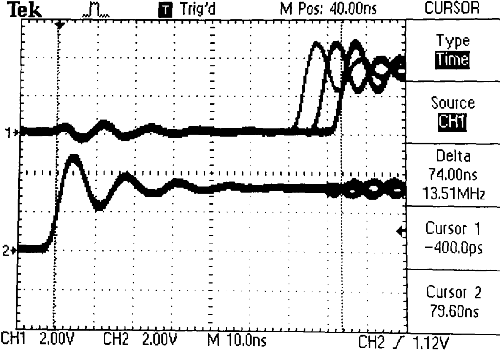
Connecting two channels of an oscilloscope to pins TIM4_CH1 and PORTG_0 allows measuring the time between the generation of the interrupt and the execution of the first instruction of the ISR. As well as its jitter, this determines the worst case of latency.
In the image below, the trace 2 corresponds to the rising edge of the timer signal which triggers the interrupt, and the trace 1 corresponds to the 1st instruction of the interrupt routine: bspOutput (BSP_OUTPUT0, 1).
Latency is measured by the cursors: 74 ns.
We can also see the jitter: about 10 ns. Curiously, the jitter values are not random. With a trace persistence for a long time, only 3 values were observed.
This test was carried out with a STM32H743 at 400 MHz.
The file testzli.c in the distribution of AdAstra-RTK presents more complete examples of use of ZLI, and the result of the measurements.
Conclusion
AdAstra-RTK allows to segregate interrupts. Thus some interrupt priorities can be reserved for non kernel aware interrupts nown as ZLI.
This technique removes the software related interrupt latencies. But the hardware latencies still remain and depend on the architecture of the MCU.
Some links
ARM Nested Vector Interrupt Controller (NVIC)
beginner-guide-on-interrupt-latency-and-interrupt-latency-of-the-arm-cortex-m-processors
Some articles about interrupt latency.
https://www.sciencedirect.com/topics/computer-science/interrupt-latency